8. End Device Addressing (NAT)
8.1. What is End Device Addressing
To access End Devices via the user interface of the Connectiviy Suite the router must perform a network NAT. The reason for this is that the router uses a Local Area Network for the End Devices with corresponding IP addresses. However, the Connectivity Suite uses a Device VPN Network within a Tenant Network to connect to the devices (see Fig. 8.1). To enable communication from the Device VPN Network to the Local Area Network of the router, a NAT must be carried out. For this, the local IP range of the router must be translated into the Device VPN Network.
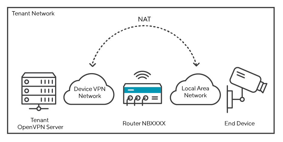
Fig. 8.1 Network setup Devices and Connectivity Suite
8.2. The Tenant Network
When adding a Tenant, you can set the size for a Tenant Network (also called Internal Network in the user interface of the Connectivity Suite) in the Connectivity Suite settings (see Fig. 8.5). The size of the Tenant Network (Internal Network) (see Fig. 8.1) defines how many devices can be connected to the Tenant. Furthermore, the Tenant Network (Internal Network) is divided into subnetworks which are called Device VPN Networks. see (see Fig. 12.1) for a graphical illustration of the Tenant Network.
8.3. The Device VPN Network
When adding a Tenant, you can define the number of End Devices to be connected to a Device (see Fig. 8.5). The defined number of End Devices defines the size of the Device VPN Network. e.g. if 256 End Devices are to be connected, the Connectivity Suite calculates the size of the Device VPN Network to /24.
However, the number of networks is limited. Since the network is a subnet of the tenant network. It is important to understand that each router has only one VPN network. Therefore, the number of Device VPN Networks that can be added also limits the number of routers that can be connected per Tenant, as only one Device VPN Network is possible per router (see Fig. 8.2).
Note
You can create more Device VPN Networks and therefore add more routers to a Tenant if you increase the Tenant Network size or reduce the number of terminals when creating a tenant.
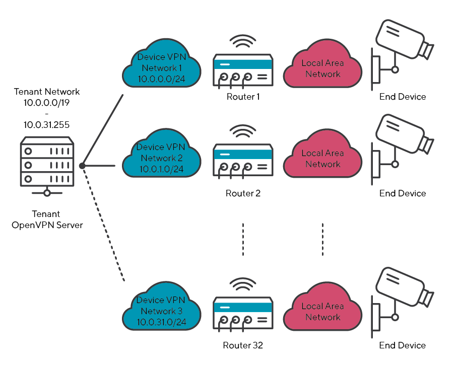
Fig. 8.2 Network Setup in Tenant Network
8.4. The Network NAT
To access the End Devices, the Device VPN Network address must be translated to a Local Area Network address. As example in Fig. 8.3, the Device VPN Network 10.0.0.0/24 is translated into the Local Area Network 172.16.0.0/24.
Warning
It is important that the subnetmask of the Device VPN Network and the Local Area Network are the same, otherwise the NAT will not work.
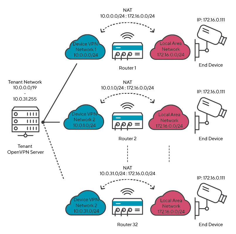
Fig. 8.3 Network Setup in Tenant Network
8.5. Use Case Example
An example of what a real-world scenario could look like is explained below.
Assumption:
Each End Device is assigned the IP address 172.16.0.111
Max. 256 End Devices will be connected to a Device
Max. 32 Devices will be connected to a Tenant
8.5.1. Considerations before configuration
To connect 256 End Devices, the Local Area Network must have a size of /24. Since all my End Devices have the same IP address of 172.0.0.111, the Local Are Network must be 172.0.0.0/24.
If the Local Ara Network has a size of /24, the VPN network must also have a size of /24 (the Ip address range of the Device VPN Network is freely selectable, whereby 10.0.0.0/24 is selected for this example).
To connect 32 routers you need 32 Device VPN Networks which have all a network size of /24 with each 256 End Devices.
If you have 32 Device VPN Networks and per Device VPN Network you have 256 End Devices this means you must be able to connect 8,192 devices to one Tenant Network therefore the Tenant Network size must be /19.
Result: If you want to connect 32 Devices and 256 End Devices per Device, you have to select a Tenant Network size of /19. Furthermore, you must perform a network NAT from your Local Area Network (17.0.0.0/24) to the Device VPN Network (10.0.0.0/24).
The network setup would look like Fig. 8.4.
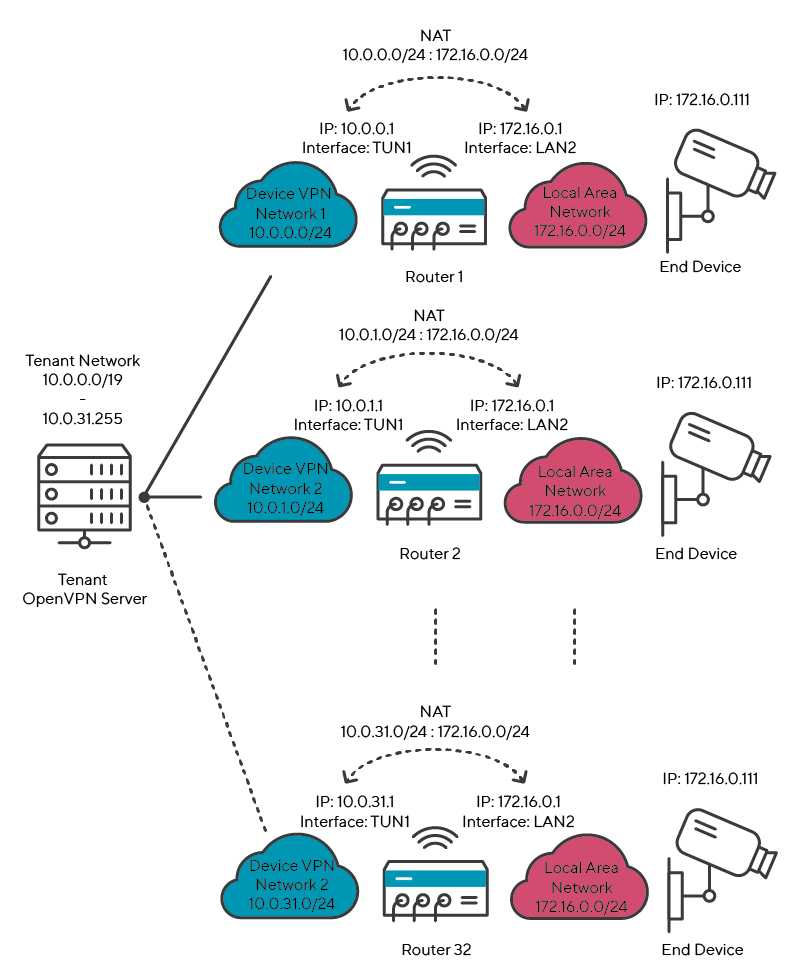
Fig. 8.4 NAT Device VPN Network to Local Area Network 2:2
8.5.2. Settings Connectivity Suite
In the Connectivity Suite, only the Tenant Network size and the number of End Devices needs to be defined so that the corresponding network can be set up.
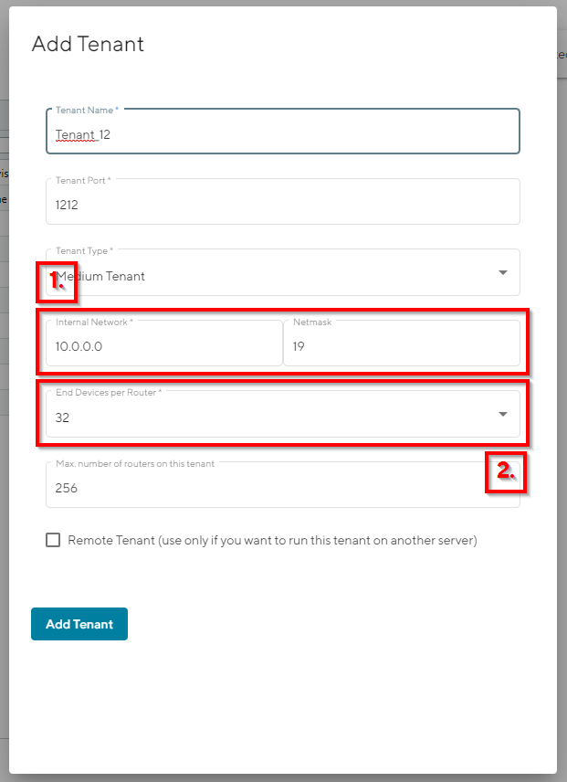
Fig. 8.5 Settings Connectivity Suite
8.5.3. Settings Router
In order to carry out a NAT, various steps are necessary which are explained below:
Open the web interface of the router, open the Firewall/Inbound Rules page and create a new rule
Select “network” for the mapping as it is required not only to translate an IP address but an entire subnet.
Select the interface. The interface must be an OpenVPN tunnel as the connection from the Device VPN Network to the Local Area Network is made via the OpenVPN tunnel of the Connectivity Suite.
Add the Device VPN Network as Target address/netmask.
Add the Local Area Network as Redirect address/netmask.
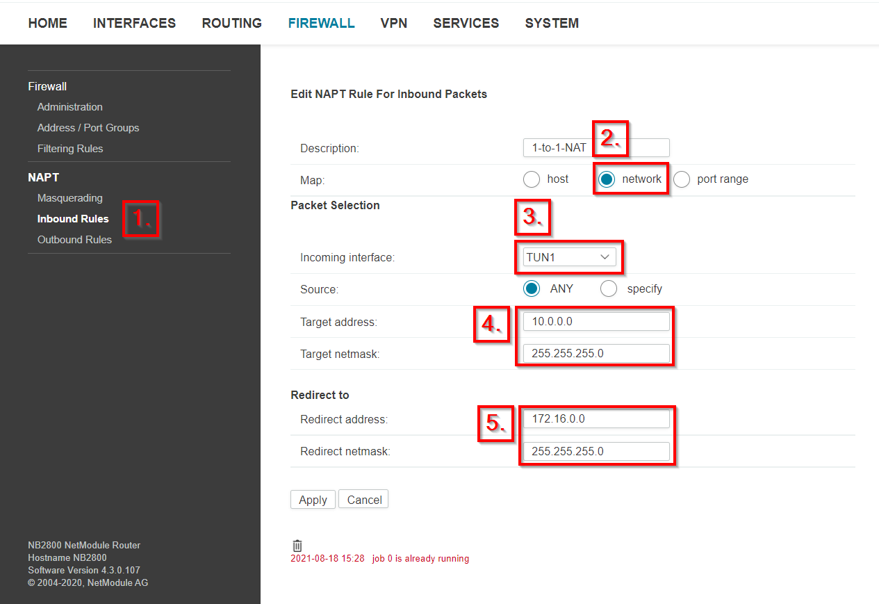
Fig. 8.6 NAT Settings NetModule Router
Save the settings. Devices that are in the Local Area Network are now displayed in the Connectivity Suite in the Device Details under Connected Devices.
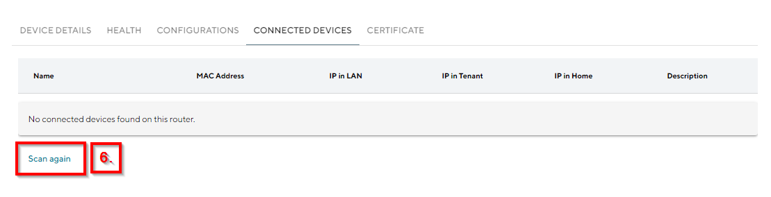
Fig. 8.7 End Devices View Connectivity Suite