4. First Setup
4.1. First Login
When logging into the Connectivity Suite for the first time, a prompt appears stating that no Tenant has been set up yet. To be able to use the Connectivity Suite it is necessary to set up a Tenant. This can be done via the “Network” page. The detailed procedure is described in Section 4.3.
If you don’t want to set up the network immediately after your first login you can get to the “Network” page anytime using the Navigation bar.
Warning
If you do not setup a Tenant, you won’t be able to assign a router to a network which means that no Jobs can be executed on the Devices.
4.2. First Network Setup
During the automatic network setup process the Home and Provisioning Server are initialized. It can take up to a minute until the Connectivity Suite detects the servers. the initial setup is now completed and the network overview on the page “Network” should look like in Fig. 4.1:
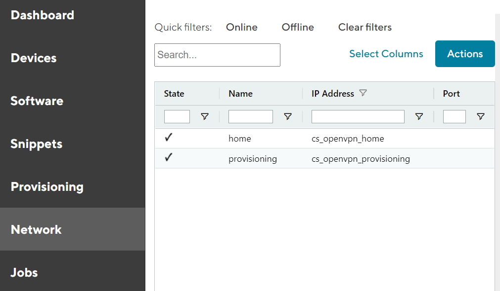
Fig. 4.1 Network overview
4.3. Adding Tenants to the Connectivity Suite
The Tenants allow logical grouping and separation of several network sites within one management platform. A Tenant ensures that devices within a Tenant can not communicate cross-tenant and therefore grant role privileges for Connectivity Suite users.
To connect routers to the Connectivity Suite it is required to add Tenants as every router needs to be assigned to a Tenant.
For the following steps an account with Platform Administrator right is required.
4.3.1. Configure the Tenant types
Between one, two or three Tenants type can be chosen depending on the layout for the Home Network (see Section 7 for more detailed explanation of the network architecture).
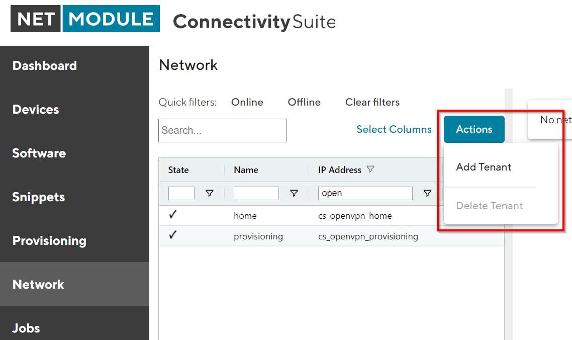
Fig. 4.2 Add Tenant
To add a Tenant, navigate to the “Network” page of the Connectivity Suite UI. Click on “Actions” at the upper right corner of the Main dialogue box and Click “Add Tenant”.
Fill out the required fields and click “Add Tenant” to start the assignment of a Tenant. A confirmation message must pop up which confirms the assignment of the Tenant.
The Tenant will now be listed in the table in the Main dialogue box. When the status shows a green tick, the Tenant is ready for use. It can take up to two minutes until the Tenant shows up in the table (see Fig. 4.3).
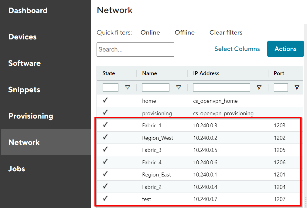
Fig. 4.3 Tenant added
Tenant Details OpenVPN Network
Shortname |
Name of the Tenant |
IP Address in Home Network |
IP address which is assigned to the tenant by the home server. |
Tenant Network |
Subnet of the tenant in the home network |
Network behind NAT |
The internal network address of the Tenant The internal network is a subnet of the Home network changed by NAT (see Section 7 for more detailed explanation). |
Port |
The UDP port number of the server where the Connectivity Suite is running (needs to be open in the firewall to connect Devices to the Tenant). |
Tenant Details Routers and End Devices
Tenant Type |
Defines the max. number of possible Tenants which can be added and max. number of Devices which can be connected to the Tenant. The Tenant type has been defined already during the installation of the Connectivity Suite and cannot be changed anymore (see Section 7.1 for more detailed explanation). |
Max. number of routers |
The maximum numbers of routers which can be connected to the Tenant. |
Number of routers left |
The number of routers that can be added to the tenant (see Section 7 for more detailed explanation). |
End devices per router |
The number of End Devices that can be connected to the tenant. |
The procedure is required for every single Tenant. The default values can be overwritten when new Tenants are created in the Connectivity Suite, i.e. these properties can be set per Tenant.
4.3.2. Adding remote Tenant
Warning
Remote Tenants are recommended when you intend to connect more than 250 devices to the Connectivity Suite. This ensures an efficient operation.
To add a Tenant, navigate to the “Network” page of the Connectivity Suite UI. Click on “Actions” at the upper right corner of the Main dialogue box and Click “Add Tenant”.
Fill out the required fields including the field “Remote Tenant” and add the domain name or IP address of the remote tenant machine, than click “Add Tenant” to start the assignment of a Tenant.
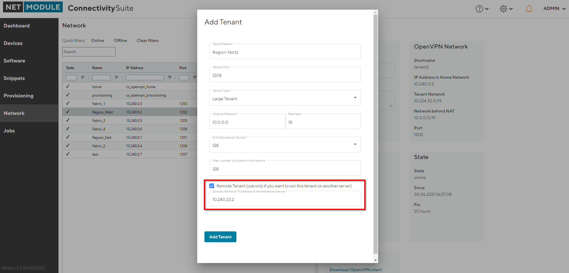
Fig. 4.4 Add Remote Tenant
Download the remote tenant installer package (this can either be done directly from the pop-up displayed right after the tenant creation or later via the Network page by clicking on the download symbol under Remote Tenant Installer next to the respective tenant (see Fig. 4.5).
After downloading the installer package, follow the instructions given in the README.txt which is included in the package.
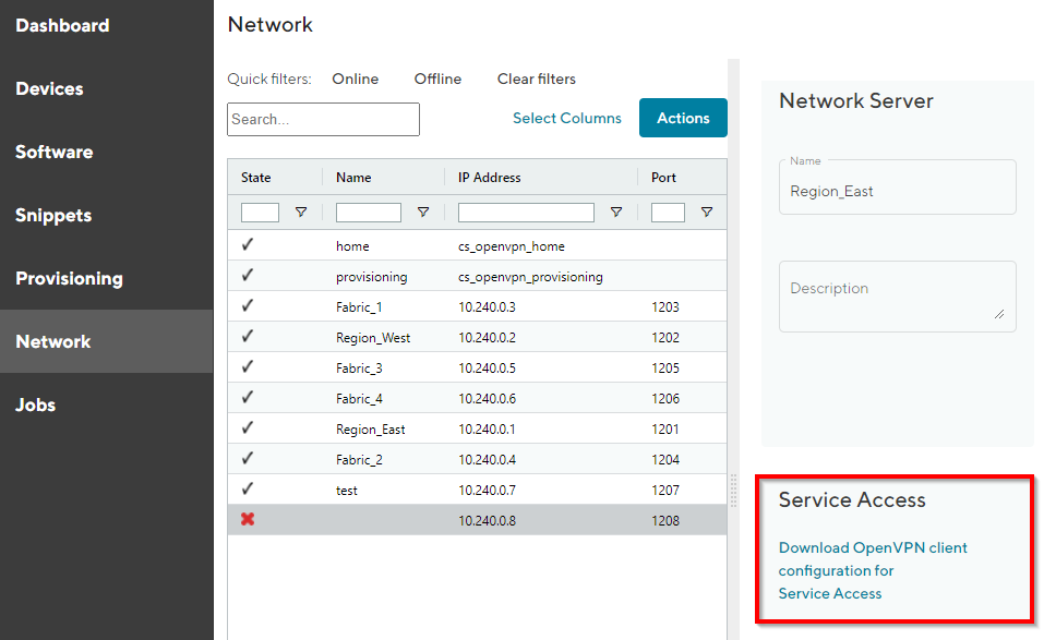
Fig. 4.5 Download Remote Tenant
4.4. Adding Routers to the Connectivity Suite
4.4.1. Supported NM router firmware releases
Before adding a router to the Connectivity Suite ensure that a supported firmware is running on the device. The Connectivity Supports the actual supported router firmware.
Note
The Connectivity Suite guarantees support for all active NM router firmware releases. These can be checked at the following link: https://wiki.netmodule.com/documentation/releases?s[]=nrsw
Older releases can also work with the Connectivity Suite, but it is recommended to update to the latest firmware as soon as possible, as support is not guaranteed for these releases.
4.4.2. Initial router provisioning
To add Devices to the Connectivity Suite they require an initial provisioning to ensure an automatic assignment of the Device to the Connectivity Suite. In this process the Provisioning Configuration for your Device is created which enables the Device to access to the Connectivity Suite. When a Device has been supplied with this configuration it automatically connects to the Provisioning Server of the Connectivity Suite via a VPN connection, the Device can than be administrated through the Connectivity Suite. The next step after the provisioning is moving the Device to a Tenant (see Section 4.5). This must be done to enable all Connectivity Suite features for a Device.
Warning
Only 250 devices can be connected to the provisioning server at once. If the provisioning server has no available space left move the connected Devices to a Tenant before adding more.
For the following steps an account with Platform Administrator rights is required.
4.4.3. Create provisioning configuration
This chapter describes how to create the configuration required by the NM router to connect automatically to the Connectivity Suite for the first time.
Steps to be executed on the web interface of the router:
Only required if the router is in factory state: Go to the Web Manager of your NM router and set an administrator password.
Only required if the router is in factory state: Set the NM router to WAN mode and change the firewall settings accordingly.
Download the current configuration from the NM router via the web interface and make sure the device is connected to the internet. This file will be needed to upload it to the Connectivity Suite
Steps to be executed on the web interface of the Connectivity Suite:
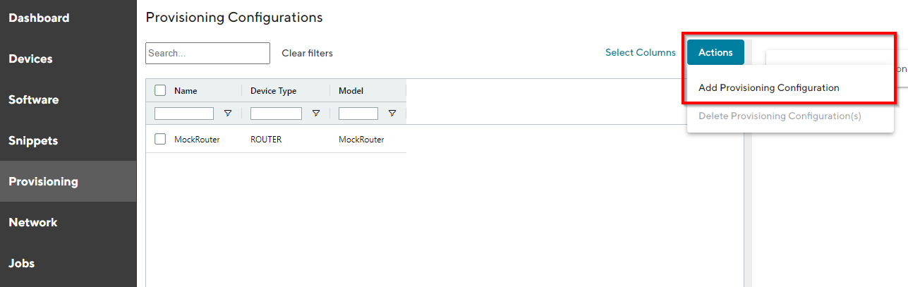
Fig. 4.6 Add Provisioning Configuration
For the initial NM router provisioning navigate to the page “Provisioning” on the Dashboard. Click on “Actions” at the upper right corner of the Main dialogue box and Click “Add Provisioning Configuration”.
Fill out the required fields and Import the configuration file that has been downloaded from the NM router by click on “Browse…”.
Click “Generate Provisioning Configuration” to upload the configuration to the Connectivity Suite. A confirmation message must pop up which confirms the upload of the configuration.
The uploaded configuration will be shown in the Main dialogue box in the table:
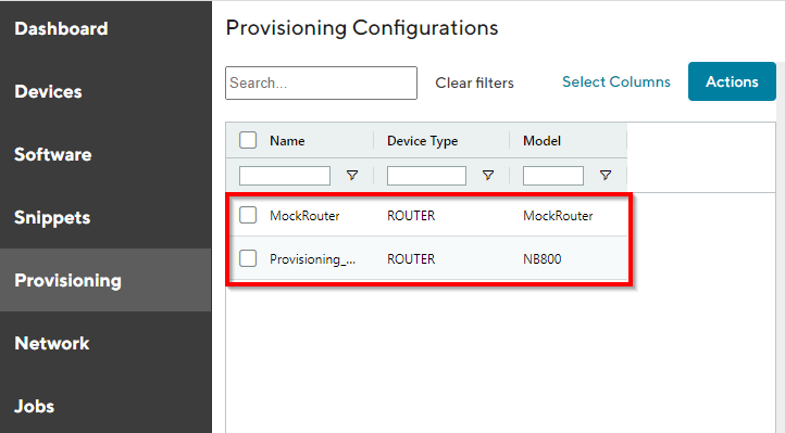
Fig. 4.7 Configuration table
4.4.4. Add provisioning configuration the NM router
Warning
The configuration used to provision the router must originally be generated from the same router model. Example: it is not allowed to upload router configurations from a NB1600 and use this configuration to provision a NB800.
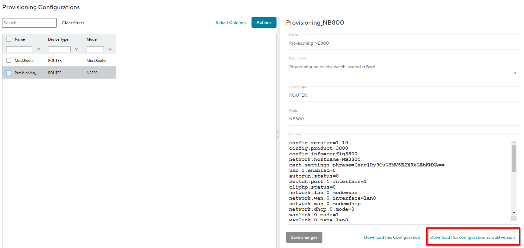
Fig. 4.8 Manual USB update
Select the required configuration in the Main dialogue box.
Click on “Download this configuration as USB version” in the lower right corner of the Detail dialogue box to download the provisioning configuration.
Unzip downloaded zip-file.
Copy the content of the extractet zip-file to an empty USB stick.
Warning
Do a factory reset of your NM router before uploading the configuration. This is necessary because the USB port has been disabled after your first login.
Plug the USB stick into your router to start the configuration update.
The router will now automatically apply the provisioning configuration and connect to the Connectivity Suite
As soon as all LEDs are blinking after connecting the USB stick, the USB stick can be removed.
Warning
The USB stick which is used to configure the NM router must be a FAT16/32 formatted USB stick.
4.4.5. Provisioning via the Web Manager
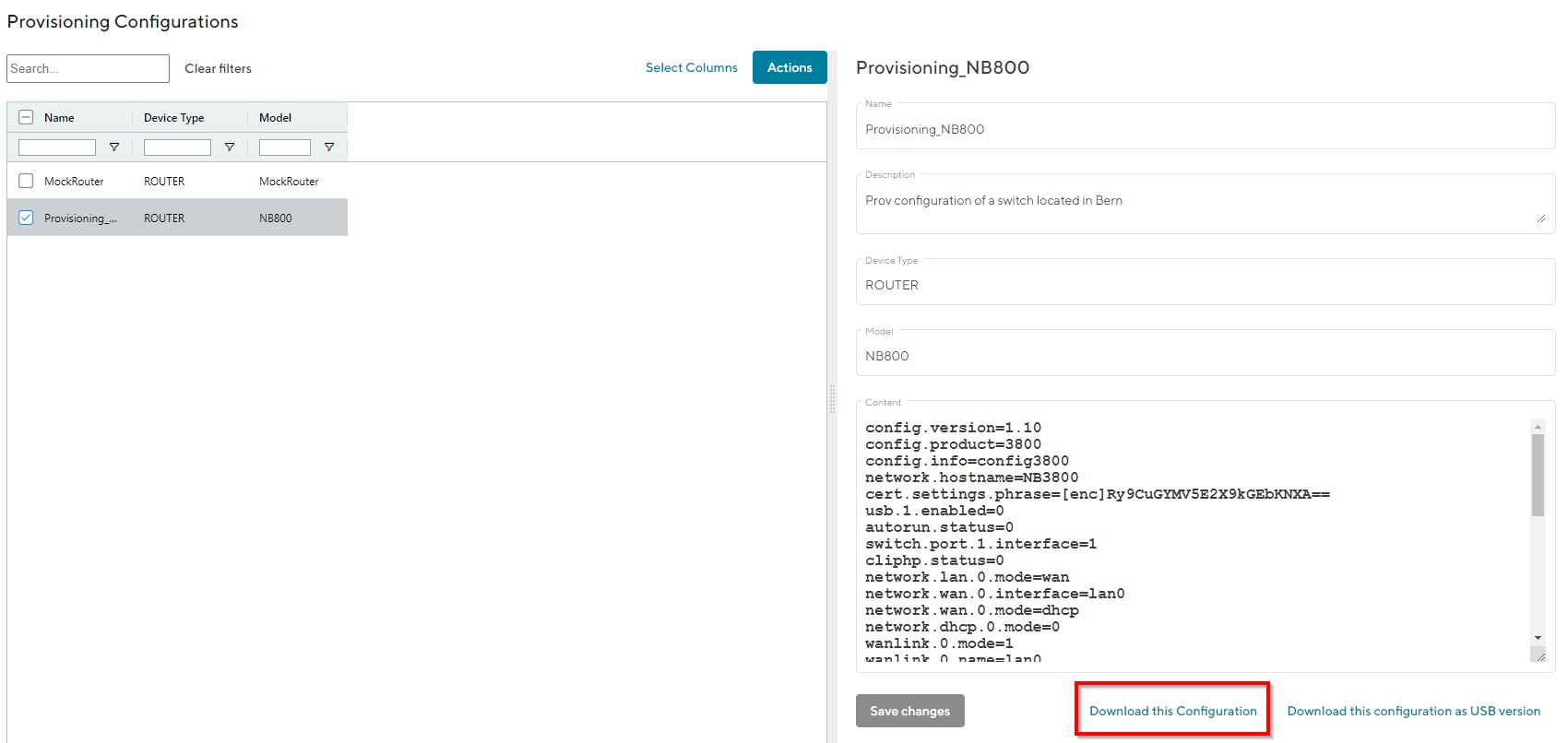
Fig. 4.9 Manuel file update
Click on “Download this Configuration” at the bottom of the Detail dialogue box to download the provisioning configuration.
Upload the file config.zip onto your NM router to start the configuration update. The configuration process starts.
The Device will now automatically connect to the Connectivity Suite.
4.4.6. Router connection check
To ensure that the Device has been connected navigate to the page “Devices” of the Connectivity Suite UI. Search for the serial number of the Device in the table of the Main dialogue box (The serial number of the Devices is automatically recognised and displayed by the Connectivity Suite). The row “state” in the table of the Main dialogue box shows whether the device has connected correctly to the Connectivity Suite. The Connectivity Suite detects to states:
tick state: The tick indicates that a Device is pingable from the Connectivity Suite Home Network. It does not indicate that all functions of the Device are working correctly.
cross state: The red cross state indicates that a Device is not pingable from the Connectivity Suite Home Network.
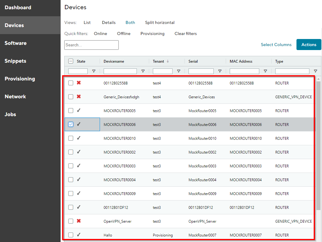
Fig. 4.10 Device overview
4.4.7. Router status check
If the device has connected correctly you can see all the Device details by clicking on the device in the table of the Main dialogue box. In the tab “Device Details” several status information about the selected Device is listed (see Fig. 4.11).
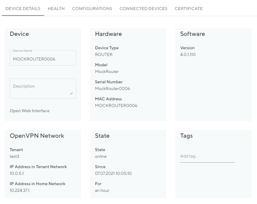
Fig. 4.11 Device Details overview
Device |
The name and description of the Device are displayed which can be customised by the user |
Hardware |
Device-specific information is displayed here which cannot be changed. |
Software |
Shows the software version which is running on the Device |
OpenVPN Network |
Shows the IP addresses of the Devices |
State |
Shows the status of the device connection with the Connectivity Suite |
Tags |
User-specific tags for further designations of devices |
Health: In the tab “Health” the connection status of the Device is displayed. The Connectivity Suite periodically pings whether the device is connected. If the connection is interrupted, the device switches from online to offline status.
Configurations: In the tab “Configuration” the actual Configuration is displayed incl. the name of the Configuration. It is also possible to modify, download or retrieve the Configuration from the Device via this tab.
Connected Devices: In the tab “Connected Devices” all End Devices are displayed which are connected to the selected Device.
Certificate: In the tab “Certificate” the validity duration of the actual valid certificate is shown. This certificate can be renewed or revoked. If the certificate is revoked the Device will lose the connection. Connectivity Suite Quick User Guide 25/48
4.5. Adding a Device to a Tenant
4.5.1. (Initial) Tenant assignment of a Device
Warning
It is recommended to connect maximum 250 devices to a Tenant to ensure an efficient operation.
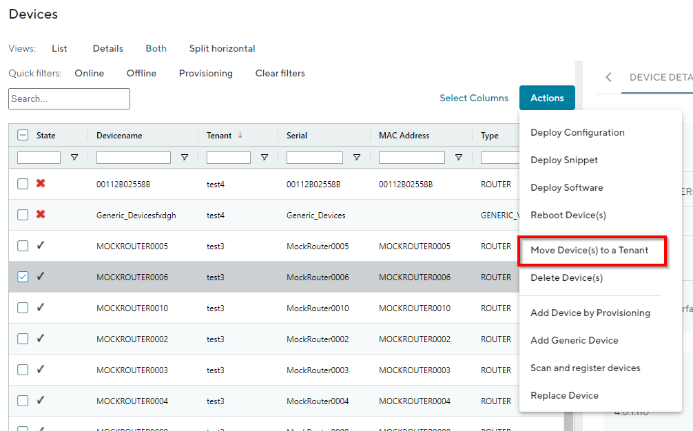
Fig. 4.12 Tenant assignment
Navigate to the page “Devices” of the Connectivity Suite and select the Devices which have to be assigned to a Tenant.
Click on “Actions” at the upper right corner of the Main dialogue box and click “Move Device(s) to a Tenant”.
Select the required Tenant in the drop down list and click “Next”.
Click on “Start assignment” to assign the Devices to the Tenant (this operation may take some time). A confirmation message must be pop up which confirms the assignment of the Devices to the Tenant.
The applied Tenant will be shown in the Main dialogue box in the table.
4.6. Connect Networks with identical IP address ranges
The Connectivity Suite provides the function to connect networks which have identical IP addresses within their subnet. This function is enabled by 1-to-1 NAT. As example all Devices within a Tenant can have the same IP-configuration.
4.6.1. 1-to-1 NAT on Tenants
While creating a new Tenant, an internal network must be provided for this Tenant. This network consists of all the Devices assigned to this Tenant, plus possible other VPN clients, like Service Access users or backend servers. Note that the same network address range can be used on multiple Tenants. The Tenants do a 1-to-1 NAT mapping, thus allowing the Connectivity Suite to individually address any Device on any Tenant (see Fig. 12.1).
4.6.2. 1-to-1 NAT on NM Routers
The concept mentioned in Section 4.6.2 also applies to the NM routers, so that multiple routers can have the same internal network address range, while the Connectivity Suite is still able to individually address any End Device behind any router (see Fig. 12.1). Therefore 1-to-1 NAT must be configured on the NM routers.