2. Installation
Warning
It is assumed that the user who is installing and setting up the Connectivity Suite has read and understood the installation prerequisites (see Section 2.1), otherwise an installation won’t be possible.
2.1. System requirements
2.1.1. Server Hardware
Warning
Insufficient system resources can cause devices to lose connection and Connectivity Suite operation can no longer be guaranteed.
2.1.2. Server Software
Instructions for Docker
Instructions for Docker Compose
Warning
Make sure that you are running at least Docker v20.x.x.
You can run docker -v to get your currently installed version.
Example output: Docker version 20.10.17, build 100c701
Make sure to configure log rotation for Docker. By default, Docker does not rotate logs and therefore the server could run out of disk space over time. A log rotation configuration example can be found in the section Docker log rotation.
Make sure that you are running at least Docker Compose v2.x.x.
You can run docker compose version to get your currently installed version.
Example output: Docker Compose version v2.10.2
Note
NetModule does not provide a full OS installer. The customer must provide it’s own, already secured, Ubuntu or Debian server with Docker and the Docker Compose plugin installed. NetModule only installs the containers.
Note
The user has to be added to the docker group. This can be done with sudo usermod -aG docker $USER and sudo su $USER
Note
In case you intend to run more than 50 VPN Networks/Servers, we recommend to increase the fs.inotify.max_user_instances limit to 512. See Section 17.2.4
2.2. Devices Compatible with Connectivity Suite
Router Product Lines
NetModule NB8xx
NetModule NG8xx
NetModule NB1xxx
NetModule NB2xxx
NetModule NB3xxx
Compatibility with Connectivity Suite is given with the following Router Models and coresponding Router Software.
Router models: https://wiki.netmodule.com/documentation/overview
Router Software versions: https://wiki.netmodule.com/documentation/releases#active-releases
WiFi Access Points
NetModule AP3400
Switches
NetModule ES3300
Tronteq ROQSTAR 2GE+8FE M12 Managed Gigabit Switch (006-130-117)
Tronteq ROQSTAR 2GE+8FE M12 Managed Gigabit PoE Switch (006-130-118)
Tronteq ROQSTAR 4GE+12FE M12 Managed Gigabit Switch (006-130-124)
Tronteq ROQSTAR 4GE+12FE M12 Managed Gigabit PoE Switch (006-130-125)
Discontinued Models are not supported by Connectivity Suite. The full list can be found here: https://www.netmodule.com/en/support/portfolio-changes/
2.3. DNS prerequisites
2.3.1. Domain name / FQDN
A FQDN is needed which points to the IP address of the server where the Connectivity Suite is installed.
If you want to use TLS certificates issued by Let’s Encrypt, this FQDN must be publicly known and accessible.
This same FQDN is also used by the routers to connect to the Connectivity Suite as well as for the users to access the Web UI.
2.3.2. Devices CNAMEs (Subdomains)
To be able to access a Device via the web proxy (see Section 11.1) a devices CNAME DNS record is necessary. Example:
Name |
Type |
Value |
|---|---|---|
devices.cs.mycompany.com |
CNAME |
cs.mycompany.com |
If you want to use the Proxy Records feature (see Section 11.1.2) you need to create a CNAME DNS record with a wildcard in the front as well. Example:
Name |
Type |
Value |
|---|---|---|
*.devices.cs.mycompany.com |
CNAME |
cs.mycompany.com |
2.3.3. DNS Example (with Proxy Records support)
Name |
Type |
Value |
|---|---|---|
cs.mycompany.com |
A |
10.42.42.42 |
devices.cs.mycompany.com |
CNAME |
cs.mycompany.com |
*.devices.cs.mycompany.com |
CNAME |
cs.mycompany.com |
2.4. Firewall
2.4.1. Incoming Ports
The following ports must be opened for incoming connections to the server:
Protocol |
Port |
Description |
|---|---|---|
TCP |
80 1) |
Certbot (for certificate renewal) |
TCP |
443 2) |
Traefik Web Proxy (for accessing the Web UI & API) |
UDP |
50040 3) |
OpenVPN Backend Server |
UDP |
50041 3) |
OpenVPN Provisioning Server |
UDP |
Custom 3) |
OpenVPN VPN Servers (one port per VPN Network) |
Only required if you want to use TLS certificates issued by Let’s Encrypt via TLS challenge (default), if you have enabled Proxy Records a DNS challenge is used and the port is not needed.
If all the users of the Connectivity Suite UI are located inside a company network, port 443 does not need to be opened to the outside world.
If all the routers managed by the Connectivity Suite are located inside a company network, these UDP ports do not need be opened to the outside world.
Note
The router through which the Connectivity Suites accesses the internet must support the NAT loopback functionality. If this is not the case, operation of the Connectivity Suite will not be possible. A list of routers that fulfil the functionality can be found at the following link: http://opensimulator.org/wiki/NAT_Loopback_Routers
2.4.2. Outgoing Ports
The following ports must be opened for outgoing connections to the internet:
Protocol |
Port |
Description |
|---|---|---|
TCP |
21 |
Used to download the latest version of the cs-cmd |
TCP |
443 |
Used to download the latest version of the docker images and plugins. Also used to check for platform updates if enabled. |
2.5. Network Address Blocks
The Connectivity Suite requires two Network Address Blocks that do not overlap with each other or the existing company network address blocks.
The Network Address Blocks must be specified during the installation of the Connectivity Suite.
Core Address Block: must be a /20 network (4’096 addresses) used for Connectivity Suite internal services
Platform Address block: The size can be defined by the user and is used to assign each Device a platform wide unique IP-address
If there is no need to access the Child Devices, the minimum size of the Platform Address Block corresponds to the number of Parent Devices you want to connect to the Connectivity Suite.
If you want to access the Child Devices, the minimum size of the Platform Address Block is [Parent Devices] * [Child Devices].
Because the Platform Address Block will be divided into several VPN Network Address Blocks during the installation process (see Network architecture), its size cannot be smaller than 4096 addresses (a /20 network).
Note
A common setup used by customers is the Platform Address Block set to 10.224.0.0/12 and the Core Address Block set to 10.240.0.0/20. Make sure that this works with your existing infrastructure!
Fig. 2.1 shows how an infrastructure with two VPN networks and five routers including end devices can look.
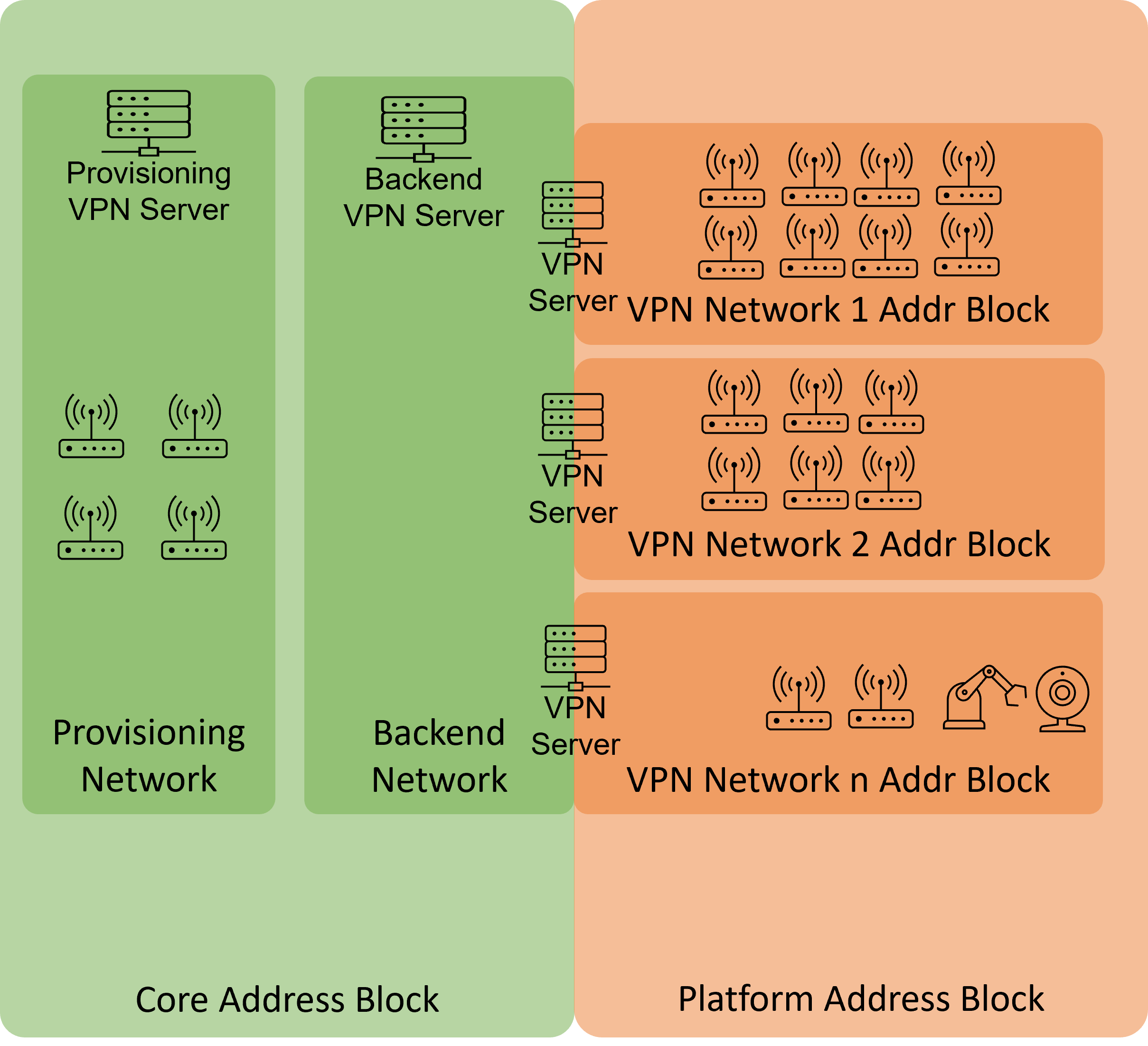
Fig. 2.1 Example system architecture
Note
The Connectivity Suite supports only IPv4. IPv6 is currently not supported.
2.6. Installing the Connectivity Suite
2.6.1. Downloading the cs-cmd
Log into your server where the Connectivity Suite will be installed
Make sure that the latest docker version is installed
Make sure that the latest docker compose plugin is installed
We recommend to install the Connectivity Suite into ~/cs
mkdir csChange to the cs directory
cd csDownload the cs-cmd console application from the NetModule repository by calling
curl -u cs-install ftp://ftp.netmodule.com/latest/cs-cmd -o cs-cmd --ssl-reqdThe credentials for repository are provided by NetModule.
Add execution rights to the cs-cmd by calling
chmod +x ./cs-cmd
2.6.2. Running the cs-cmd Installation Assistant
Run the cs-cmd by calling
./cs-cmdChoose
Installation Assistantand press[Enter]Follow the instructions of the Installation Assistant
Warning
Attention! The following steps can only be configured during the installation and are only reversible by doing a re-installation (which means you will lose all the stored data).
Configure the Core Address Block in the format
xxx.xxx.xxx.xxx/20(e.g.10.240.0.0/20). It is mandatory to use an address block mask of 20 (see Section 12 for more detailed description).Configure the Platform Address Block in the format
xxx.xxx.xxx.xxx/xx(e.g.10.224.0.0/12) and make sure the address block is greater than 20. Also be aware that as example a address block of 20 does not mean that you will be able to connect 4096 devices there is a big reduction based on the Network Architecture. (see Section 12 for more detailed description).
Warning
Attention! The Platform Address Block restricts the amount of Devices which can be connected to the Connectivity Suite. Be aware that if the number set during this step is too small this cannot be changed afterwards.
When prompted choose between default settings for your Plattform Address Block layout or create a layout by yourself. If you choose the default settings step 7-12 can be skipped. Be aware, that only experienced users should do the settings in step 7-12.
Choose your preferred Plattform Address Block layout (you have the option of three given layouts).
Enter a name for the VPN subnet Pool type.
Enter the number of max. required VPN networks. Be aware that if the number set during this step is too small this cannot be changed afterwards.
Configure the size of the VPN Network Address Block in the format
xxx.xxx.xxx.xx/xx.Enter the number of max. required End Devices. Be aware that if the number set during this step is too small this cannot be changed afterwards.
Enter the number of concurrent Service Access sessions. This defines how many users can establish an OpenVPN connection to the same VPN network at the same time. This value is set per pool and applies to all VPN networks created from this pool. The default setting is 4.
Note
The setting for number of concurrent Service Access sessions cannot be changed later.
It it also important to know that for Service Access, always the last IP addresses of the VPN network are used. Example: for a 10.0.0.0/21 VPN network with the default setting of 4 concurrent Service Access sessions, the addresses 10.0.7.250 to 10.0.7.253 are used for Service Access (10.0.7.254 is the address of VPN server). This means that you must be careful not to set this number too high for very small VPN networks, as otherwise address conflicts with device VPN addresses may occur.
Note
Step 8-12 may need to be repeated, depending on the chosen Platform Address Block layout in step 7.
Choose if you want Let’s Encrypt or the Connectivity Suite certification authority to be used to issue the SSL certificate to access the UI. If you already have your own certificate infrastructure you can choose to use your own certificates for TLS.
Note
If you choose the Connectivity Suite certification authority to issue the SSL certificate, it is not required for port 80 to be open for incoming connections in your firewall! However, your browser is going to display a warning the first time you open the Connectivity Suite UI. This is normal behaviour. In order to make this warning disappear, your browser needs to trust the Connectivity Suite Root Certification Authority. The procedure varies for different browsers (see Section 17.2.5).
Note
If you create your own TLS certificate for the Connectivity Suite, the following applies:
The Subject Name is the FQDN of the server running the Connectivity Suite.
The Subject Alternative Names contain two entries:
The same FQDN as above
The same FQDN as above prefixed with devices. (i.e. if the FQDN is cs.mydomain.com, this entry is devices.cs.mydomain.com)
Place the certificate and its key in the files
cs/app/app-data/traefik/data/default.crtcs/app/app-data/traefik/data/default.key
If you use other filenames,
cs/app/app-data/traefik/data/dynamic_conf.ymlhas to be adapted accordingly.Restart Traefik to activate your certificate:
docker restart traefik01
Advanced options: If you want to adjust the OpenVPN Default Ports or have some custom MTU sizes (OpenVPN fragment / MssFix)
Once the installation has finished, you can log into your newly installed Connectivtiy Suite instance with the url, username and password provided in the console output.
You will be asked to change the password. Make sure to store the username and password in a save place
Note
For details regarding the network configuration and layout see Network architecture.
Note
The username is randomly generated. It is thought as the main admin account, used only to create personal users for each platform admin