6. Device Management
The Connectivity Suite can manage and administer different types of devices. Successfully onboarded devices are listed in the Device Inventory
6.1. Device Inventory & Status
A customizable table view provides an overview of all devices. The columns in the table can be configured using the column chooser. (see Fig. 6.1)
6.1.1. Connection Status
The following codes indicating the connection states:
State Green: Connection is up and device can be accessed by Connectivity Suite.
State Red: Indicates that the device is not pingable from Connectivity Suite.
State Unknown: Devices that have been migrated from an older CS software version get “unknown” connection state. Once these devices have successfully established a connection, they become green and red respectively. Devices after a migration, that never establish a connection remain in “unknown” state.
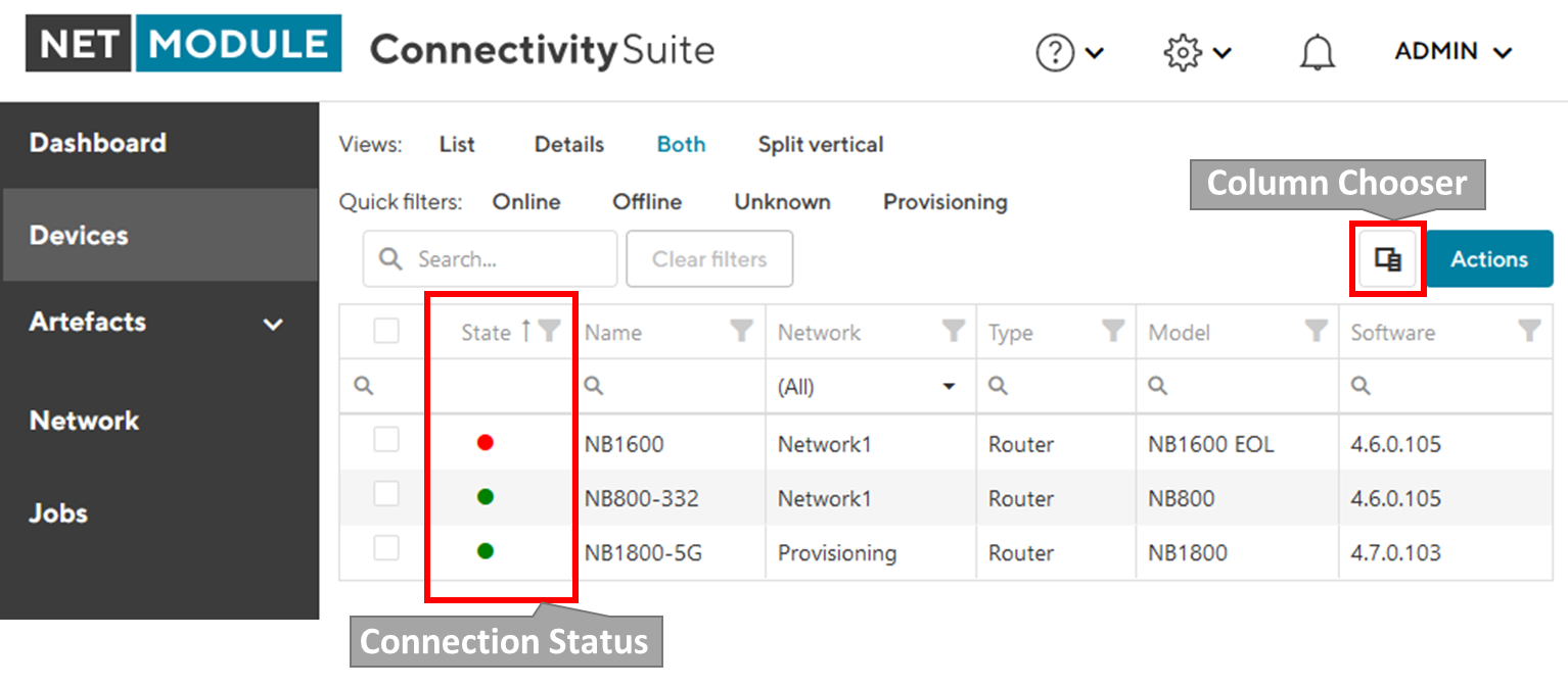
Fig. 6.1 Device List
6.1.2. Device Details Page
The device details page has multiple tabs with information about the device’s status and parameters.
6.1.3. Device Details Tab
The “Device Details” tab provides status information, hardware and software details, network information, tags, custom routes, storage information, mobile network module details, WLAN details, WAN & LAN interface details, VPN connections, GNSS module information, and enabled/disabled software features.
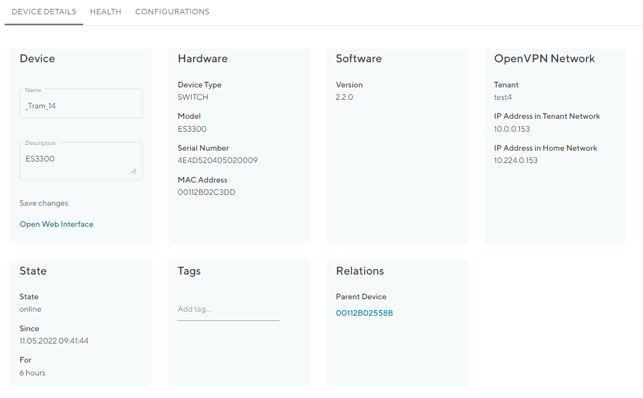
Fig. 6.2 Device Details overview
Device |
Device name and description, which can be edited Direct Web UI access of device Refresh Device Data (Update Device Info) |
Hardware |
Device-specific information is displayed here which cannot be changed. |
Software |
Shows the firmware version which is running on the Device |
Firmware |
Firmware version |
Network |
Shows the assigned IP addresses of the Devices |
State |
Shows the status of the device connection with the Connectivity Suite |
Tags |
User-specific tags for further designations of Devices |
Custom Routes |
If enabled under global settings, custom routes may be set here. |
Storage |
If present, storage info to total size, used & available memory |
Mobile |
Indicates number of Mobile Network Modules, as well as corresponding statusinfo: - Modem operational Status - SIM card - IMEI, IMSI |
WLAN |
If present, it provides an overview on: - Module Type - Operation modes (WiFi Standards) |
WAN & LAN |
Interface details, with port count and relative status with IP Address info. |
VPN |
VPN connections, with type info, relative status, assigned IP Addresses |
GNSS |
If present, module information is listed here |
Features |
Overview of software features that are enabled or disabled |
Health
In the tab “Health” the connection status of the Device is displayed. The Connectivity Suite periodically pings whether the device is connected or not. If the connection is interrupted, the status switches from online to offline. The meaning of the colored status is as follows: Green = Connected / Online Yellow = Intermittent connection Red = Disconnected
The yellow state indicates intermittent reconnections within a given timeframe. Depending on the use-case, this may be a normal behavior (device is moving, e.g. installed on a train), in which no action is required.
Configurations
In this tab, configurations associated with the selected device are displayed. New configurations can be uploaded and existing ones can be edited or downloaded. The current configuration can be retrieved from the device. Selecting two configurations allows to compare them side-by-side.
However, applying a configuration to the selected device has to be done with a configuration deployment (see Section 6.4.1).
Connected Devices
Devices connected to the LAN, may be discovered usign the scan function.
Certificate
In addition to the certificates validity being displayed on that tab, certificates can be either revoked or renewed. Revoking a certificate causes the device conneciton to be disconnected. This action might be useful when due to whatever reason the device has been compromised.
Logs
Device Logs viewer and export function.
6.2. Device Configuration Handling
Several actions related to the configuration of devices are available and described thereafter.
6.2.1. Variables
6.2.2. Copy Device configurations
Using the Connectivity Suite, configurations can be copied from one Device to another Device of the same Model. To copy configurations across devices, follow the instructions below:
Navigate to the page “Devices” of the Connectivity Suite and select the Device in the table of the Main dialogue box from which the configuration is to be copied.
Click on “Actions” at the upper right corner of the Main dialogue box and click “Download this configuration” (configuration can be uploaded via the web manager) or “Download this Configuration as USB version” Configuration can be uploaded via an usb stick).
Select the Device in the table of the Main dialogue box to which the downloaded configuration is to be copied.
Click on “Actions” at the upper right corner of the Main dialogue box and click “Upload configuration”.
Select the downloaded configuration from step 2 and click “Uploade Device Configuration”
Click on “Actions” at the upper right corner of the Main dialogue box and click “Deploy Configuration”.
Select the configuration version to be deployed from step 5.
Select whether you want to start the configuration immediately or whether it should be scheduled.
Confirm the deployment by click “Start deployment”. The job can be started (b) immediately or (a) scheduled.
6.2.3. Restore configuration
Each time a standard configuration is changed, a new configuration version is created rather than overwriting the current configuration. The different configuration versions can be seen on the page “Devices” in the Detail dialogue box in the tab “Configurations”.
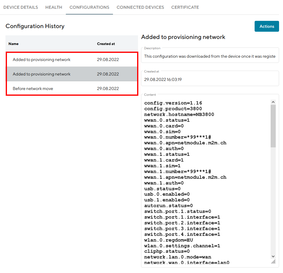
Fig. 6.3 Configuration versioning
The Connectivity Suite creates a configuration version when following happens:
If a Device connects for the first time with the Connectivity suite
If the Connectivity Suite has executed a configuration update
When a Device is moved to a network
Before the Connectivity Suite performs a configuration update (backup copy)
If you want to restore an old configuration follow the following steps:
Navigate to the page “Devices” of the Connectivity Suite and Select the Device on which an old configuration is to be restored.
Click on “Actions” at the upper right corner of the Main dialogue box and click “Deploy Configuration”.
A list of all configuration versions of the Device is displayed. Select the configuration version to be restored.
Select whether you want to start the configuration immediately or whether it should be scheduled.
Confirm the deployment by click “Start deployment”.
6.2.4. Manual configuration updates
There are a few cases where the Connectivity Suite does not capture a Device configuration change, with the current Configuration stored in the Connectivity Suite does not correspond to the one running on the Device and must be manually updated:
If the change was made outside of the Connectivity Suite (e.g. via the web interface of a NM router or the router CLI)
If an older configuration version has been deployed
In those cases, the user must manually trigger the import of the updated configuration to the Connectivity Suite.
Navigate to the page “Devices” and select in the Main dialogue the Device for which the configuration has changed
Open the tab “Configurations”, click on “Actions” at the upper right corner of the Detail dialogue box and click “Retrieve current configuraton from device”.
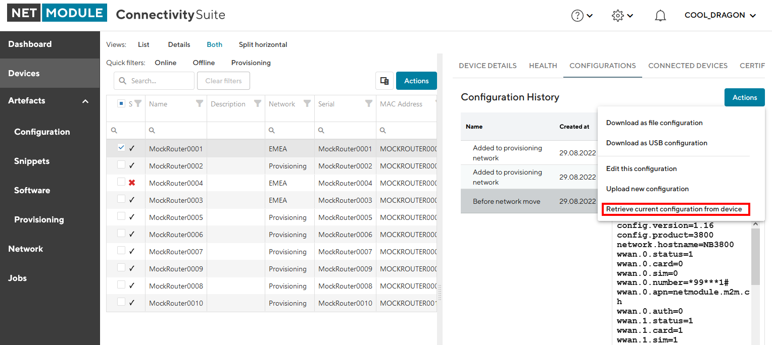
Fig. 6.4 Retrieve user configuration
Choose “Import current device configuration into Connectivity Suite” in the pop-up window. The configuration is now listed in the configuration history table.
6.2.5. Install provisioning configuration on a device
Select the required configuration in the Main dialogue box.
Click on “Download this configuration as USB version” to download the provisioning configuration.
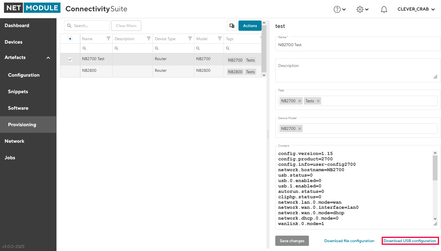
Fig. 6.5 Manual USB update
Unzip downloaded zip-file.
Copy the content of the extractet zip-file to an empty USB stick.
Warning
Make sure the USB port is activated. After your first login the USB port will be disabled per default.
Plug the USB stick into your router to start the configuration update.
The router will now automatically apply the provisioning configuration. As soon as all LEDs are blinking after connecting the USB stick, the USB stick can be removed.
The router connects now automatically to the Connectivity Suite.
Warning
The USB stick which is used to configure the NM router must be a FAT16/32 formatted USB stick.
6.2.6. Provisioning via the Web Manager
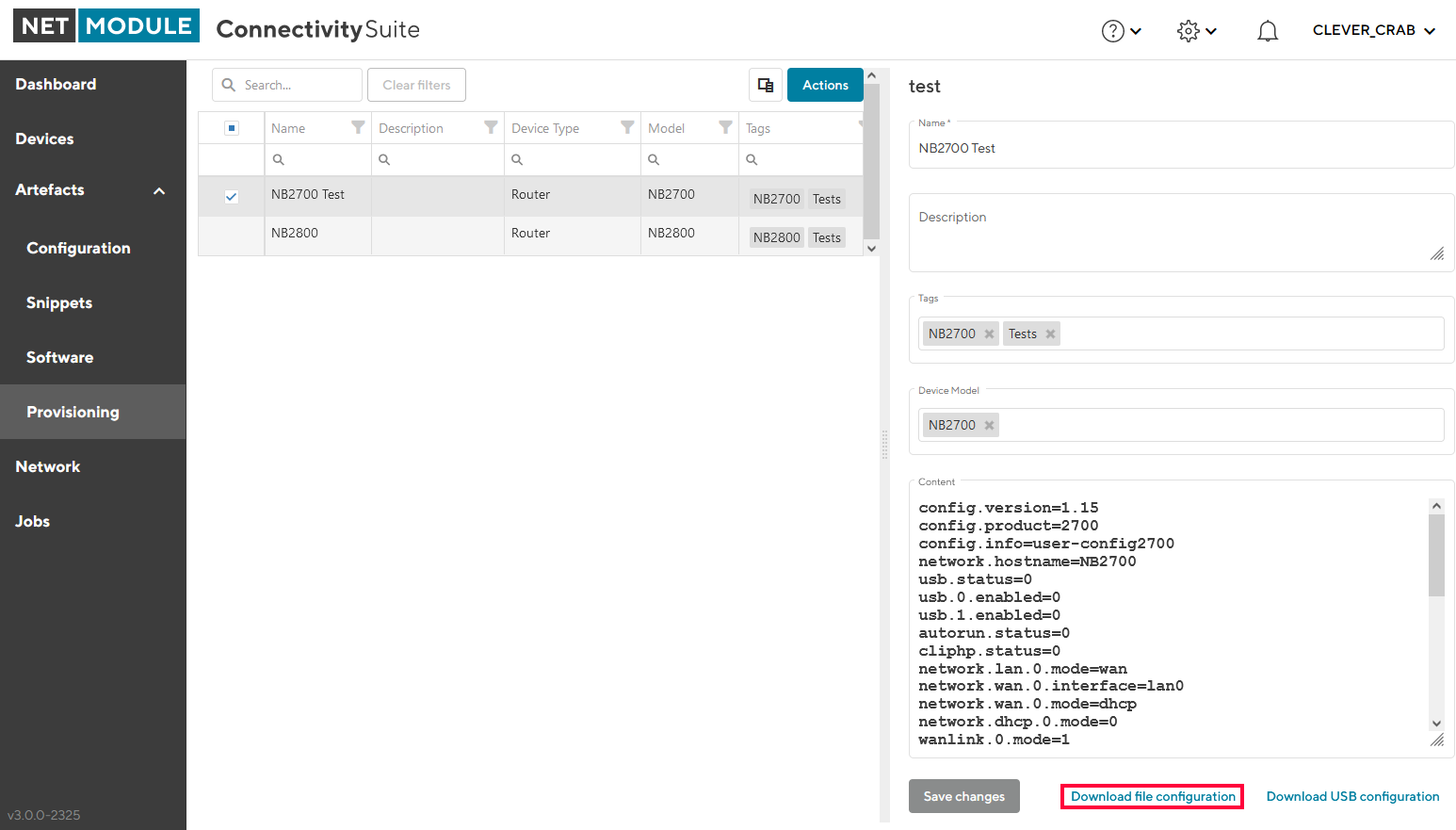
Fig. 6.6 Manual file update
Click on “Download this Configuration” at the bottom of the Detail dialogue box to download the provisioning configuration.
Upload the file config.zip onto your NM router to start the configuration update. The configuration process starts.
The Device will now automatically connect to the Connectivity Suite.
6.3. Compare configurations
There are two ways for selecting and comparing configurations:
Compare two configurations of the same device or type
Compare any two configurations
6.3.1. Compare two configurations of the same device or type
This action can be done in the following lists:
Configurations of a specific device
Artefacts / Configuration
Artefacts / Provisioning
Select two configurations in one of these lists and choose “Compare selected configurations” from the “Actions” menu:
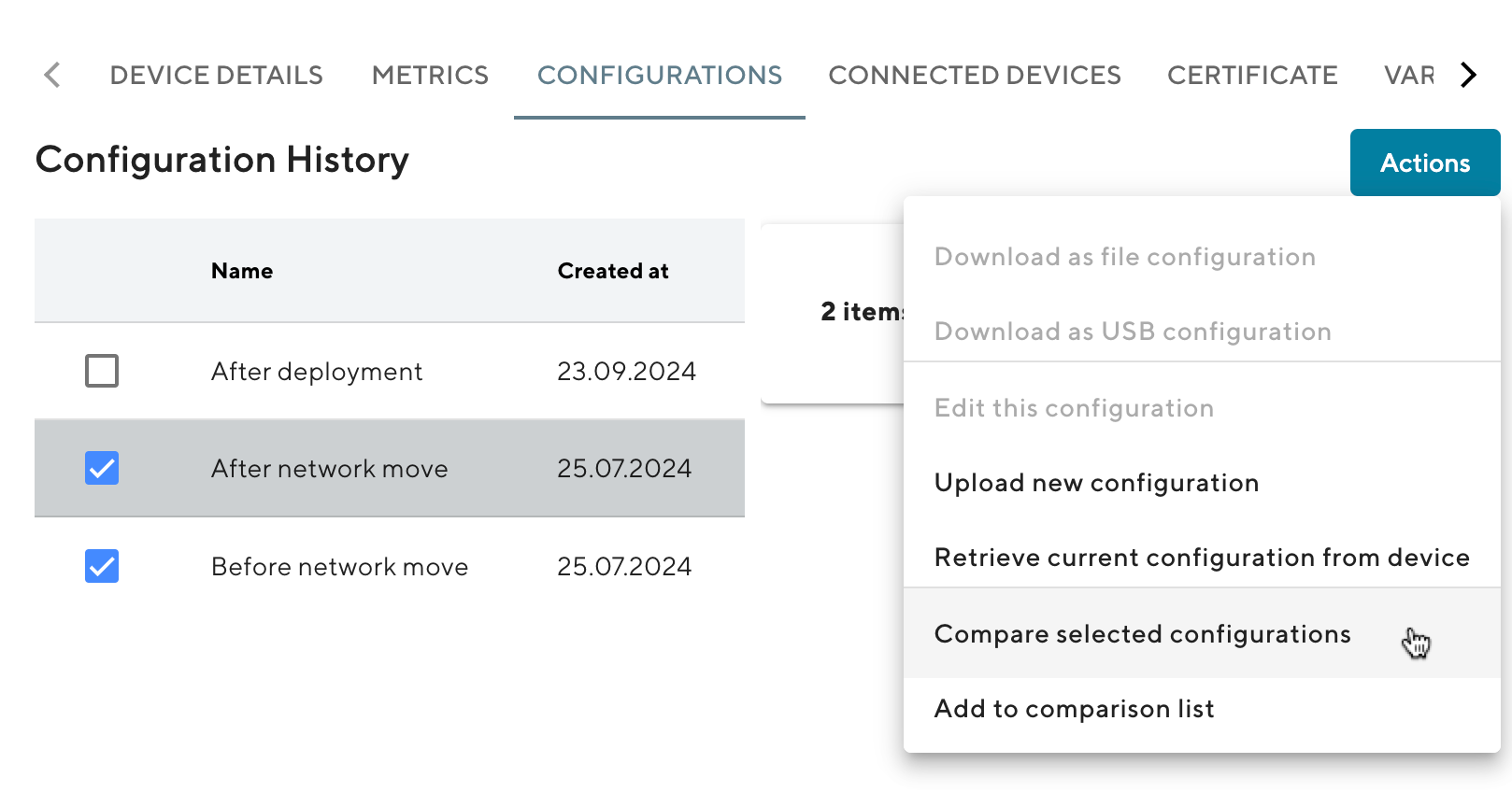
Fig. 6.7 Compare two configurations of the same device or type
The “Configurations Comparison” window opens, showing the selected configurations side by side and highlighting the differences:
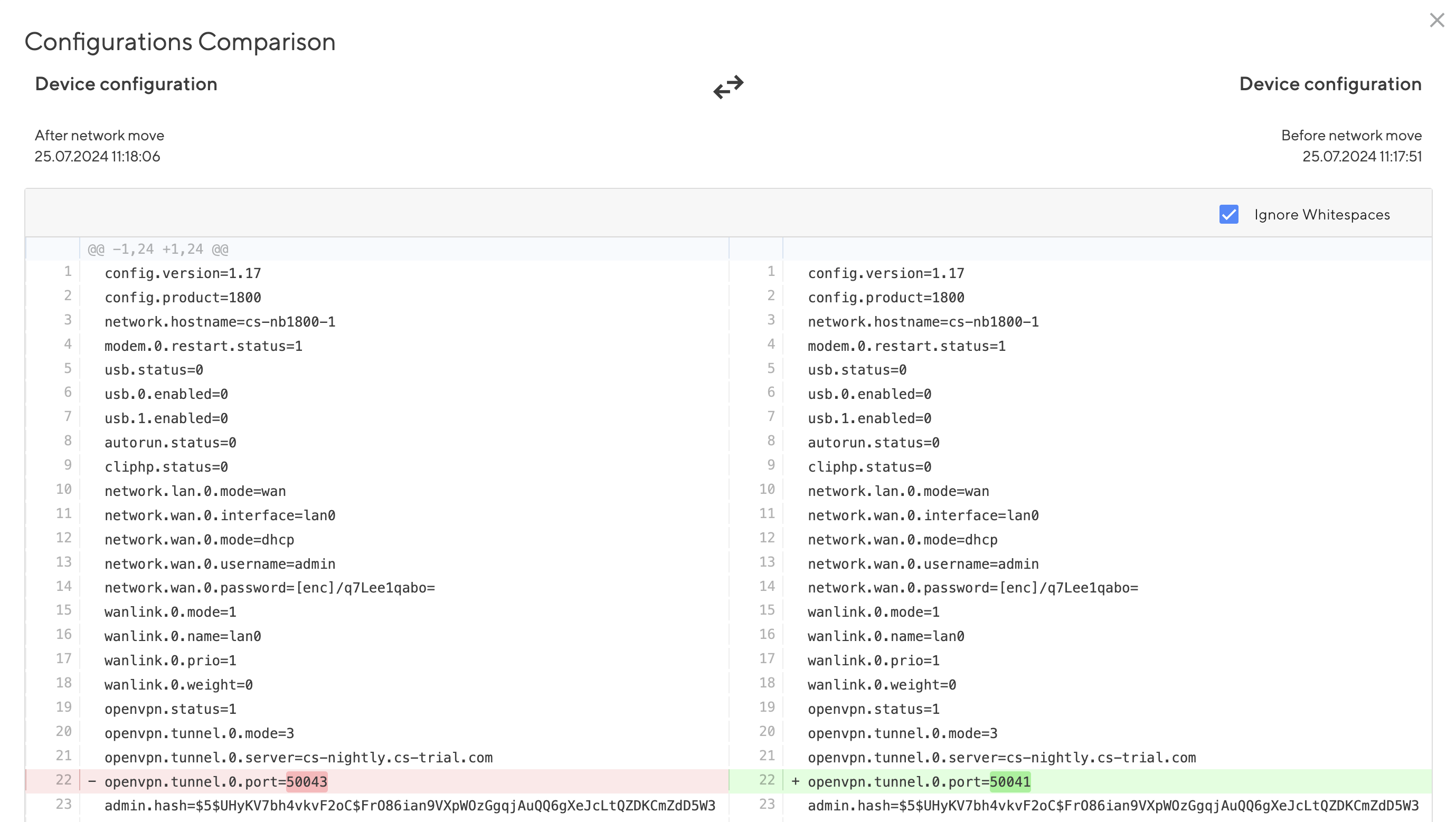
Fig. 6.8 Configurations Comparison
In this window, you can
swap the left and right side
choose to show also whitespace differences (these are ignored by default)
6.3.2. Compare any two configurations
In any list of configurations, select a configuration and choose “Add to comparison list” from the “Actions” menu:
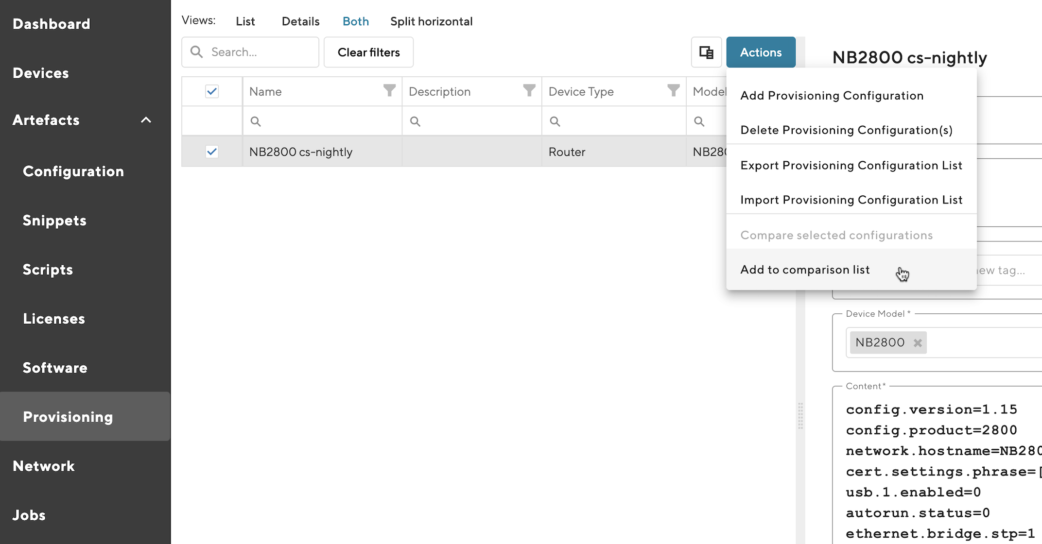
Fig. 6.9 Add to comparison list
Add a second configuration to the comparison list in the same way.
Note the icon ![]() in the icon bar, indicating that there are two configurations in the comparison list.
in the icon bar, indicating that there are two configurations in the comparison list.
By clicking on this icon, the Compare slide-out appears and shows the comparison list:
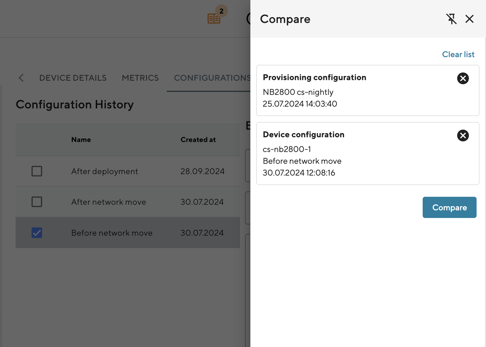
Fig. 6.10 Compare slide-out
In this slide-out, you can
clear the whole list
remove individual entries
compare the two configurations in the list
By clicking the “Compare” button, the same “Configurations Comparison” window opens as described above.
6.4. Generic Device actions
6.4.1. Deploy a Configuration
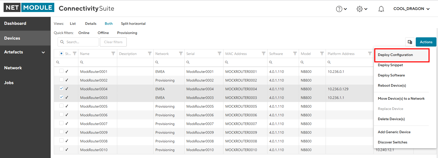
Fig. 6.11 Deploy Configuration Action
Navigate to the page “Devices” of the Connectivity Suite and select the Devices which should received a new Device Configuration.
Click on “Actions” at the upper right corner of the Main dialogue box and click “Deploy Configuration”.
Chose a configuration you want to deploy. If you have selected a single device, you can choose between previous configuration versions or Template Configurations. If you have chosen multiple devices, only Template Configurations are available for deployment.
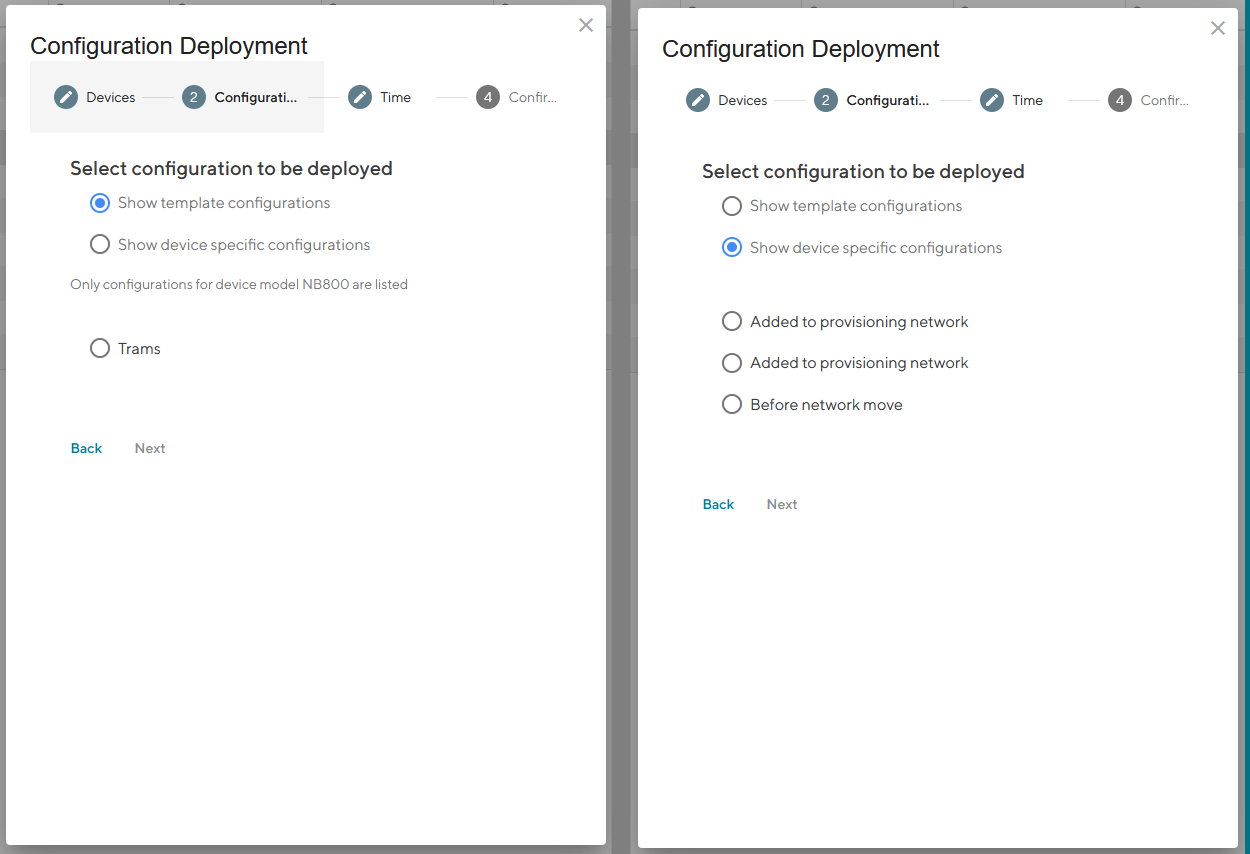
Fig. 6.12 Deploy Configuration Type Selection
Select the Configuration you want to deploy and click “Next”.
Chose if you want to start the deployment immediately or if you want to schedule it for later execution and click “Next”.
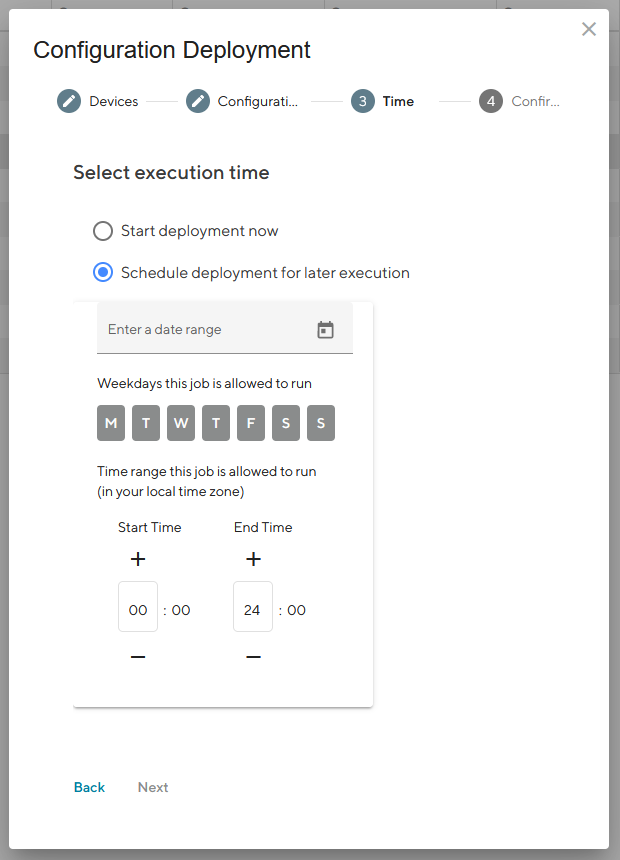
Fig. 6.13 Deploy Configuration Schedule
Check if the deployment details are correct and click “Schedule deployment”.
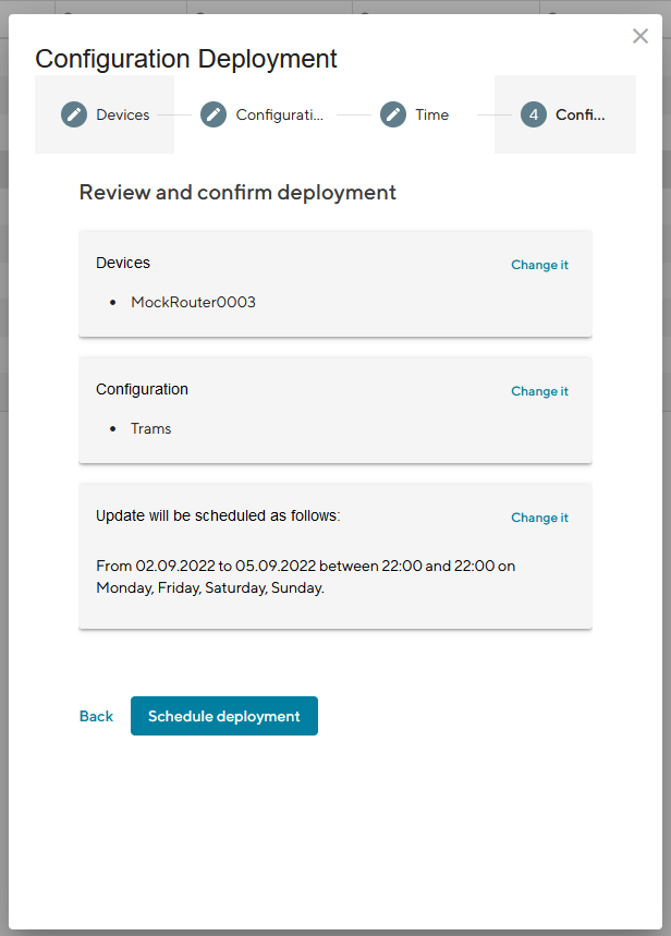
Fig. 6.14 Deploy Configuration Confirmation
6.4.2. Deploy a Snippet
Navigate to the page “Devices” and select the Devices in the main dialogue Box that are to be configured.
Click on “Actions” at the upper right corner of the Main dialogue box and click “Deploy Snippet”.
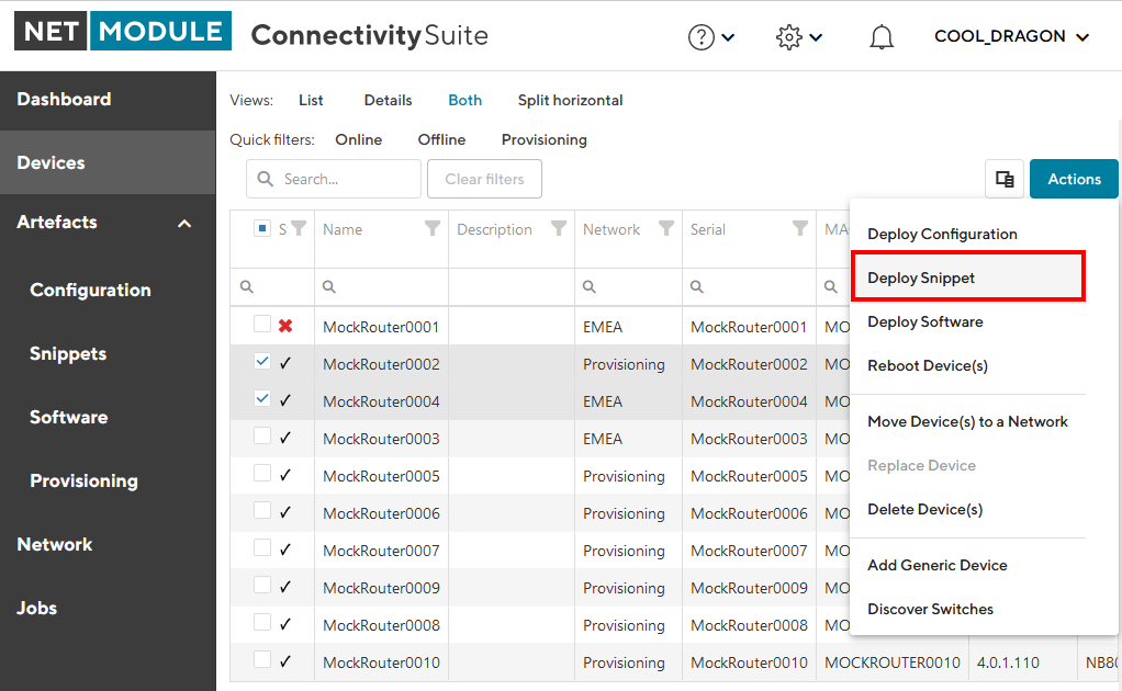
Fig. 6.15 Deploy Snippet Action
Select the Snippet to be deployed.
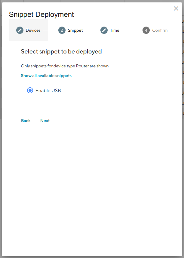
Fig. 6.16 Snippet Selection
Select whether you want to start the configuration immediately or whether it should be scheduled.
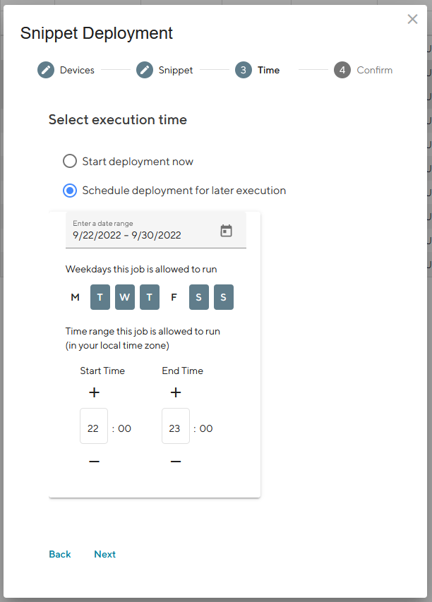
Fig. 6.17 Snippet Deployment Schedule
Confirm the deployment by click “Start deployment”.
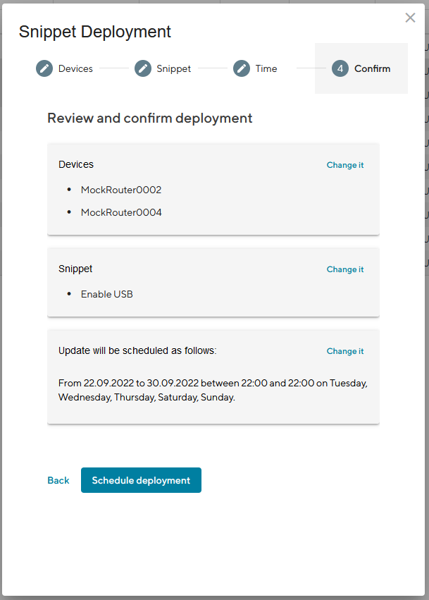
Fig. 6.18 Snippet Deployment Confirmation
When a Snippet deployment has started it will be listed as a Job in the Jobs table (see Section 10). Jobs can be scheduled while creating them (see step 7). Therefore following scheduling options are possible:
Start Date |
The first day on which the Connectivity Suite is going to try to execute the Job, if all conditions are met (time window, day of the week etc.). |
End Date |
The last day on which the Connectivity Suite is going to try to execute the Job, if all conditions are met (time window, day of the week etc.). |
Days |
Offers the possibility to constrain the execution of the Job to specific days of the week. By default, the execution is allowed for all days of the week (the blue color indicates a selected day) |
Start Time |
Offers the possibility to constrain the Job execution to a certain time frame within a day. Only the hour can be specified, higher precision is not supported currently. Allowed values are 0-23, the default value is 0 (midnight). |
End Time |
Offers the possibility to constrain the Job execution to a certain time frame within a day. Only the hour can be specified, higher precision is not supported currently. Allowed values are 1-24, the default value is 24 (midnight). |
Warning
Configuration changes made in the web interface of the Device will not be automatically added to the Connectivity Suite and can lead to connectivity issues. Any configuration changes made in the web interface of a NM router must be uploaded to the Connectivity Suite as described in ::manual_configuration_updates.
6.4.3. Deploy Software
Navigate to the page “Devices” and select the Devices in the main dialogue Box that are to be updated.
Click on “Actions” at the upper right corner of the Main dialogue box and click “Deploy Snippet”.
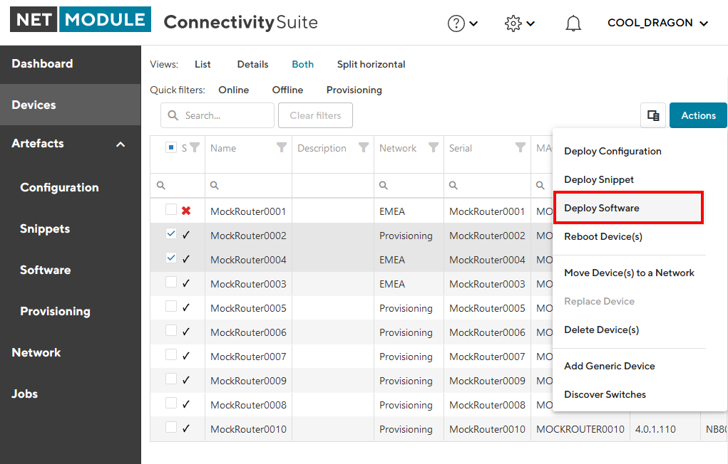
Fig. 6.19 Deploy Software Action
Select the Software to be deployed.
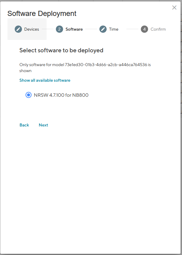
Fig. 6.20 Software Selection
Select whether you want to start the configuration immediately or whether it should be scheduled.
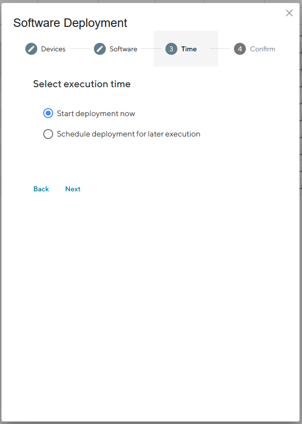
Fig. 6.21 Software Deployment Schedule
Confirm the deployment by click “Start deployment”.
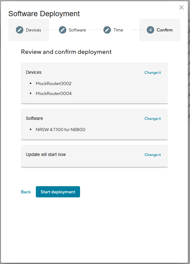
Fig. 6.22 Software Deployment Confirmation
When a Software deployment has started it will be listed as a Job in the Jobs table (see Section 10). Jobs can be scheduled while creating them (see step 7). Therefore following scheduling options are possible:
Start Date |
The first day on which the Connectivity Suite is going to try to execute the Job, if all conditions are met (time window, day of the week etc.). |
End Date |
The last day on which the Connectivity Suite is going to try to execute the Job, if all conditions are met (time window, day of the week etc.). |
Days |
Offers the possibility to constrain the execution of the Job to specific days of the week. By default, the execution is allowed for all days of the week (the blue color indicates a selected day) |
Start Time |
Offers the possibility to constrain the Job execution to a certain time frame within a day. Only the hour can be specified, higher precision is not supported currently. Allowed values are 0-23, the default value is 0 (midnight). |
End Time |
Offers the possibility to constrain the Job execution to a certain time frame within a day. Only the hour can be specified, higher precision is not supported currently. Allowed values are 1-24, the default value is 24 (midnight). |
6.4.4. Reboot a Device
Navigate to the page “Devices” and select the Devices in the main dialogue that are to be rebooted.
Click on “Actions” at the upper right corner of the Main dialogue box and click “Reboot Device(s)”.
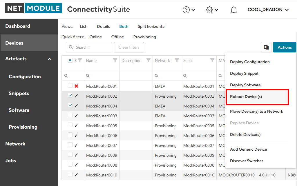
Fig. 6.23 Reboot Devices Action
Confirm the reboot by clicking “Reboot device(s)”.
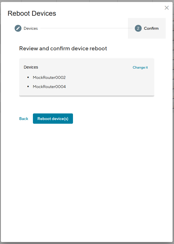
Fig. 6.24 Reboot Devices Confirmation
When a Reboot has started it will be listed as a Job in the Jobs table (see Section 10).
6.4.5. Move Network
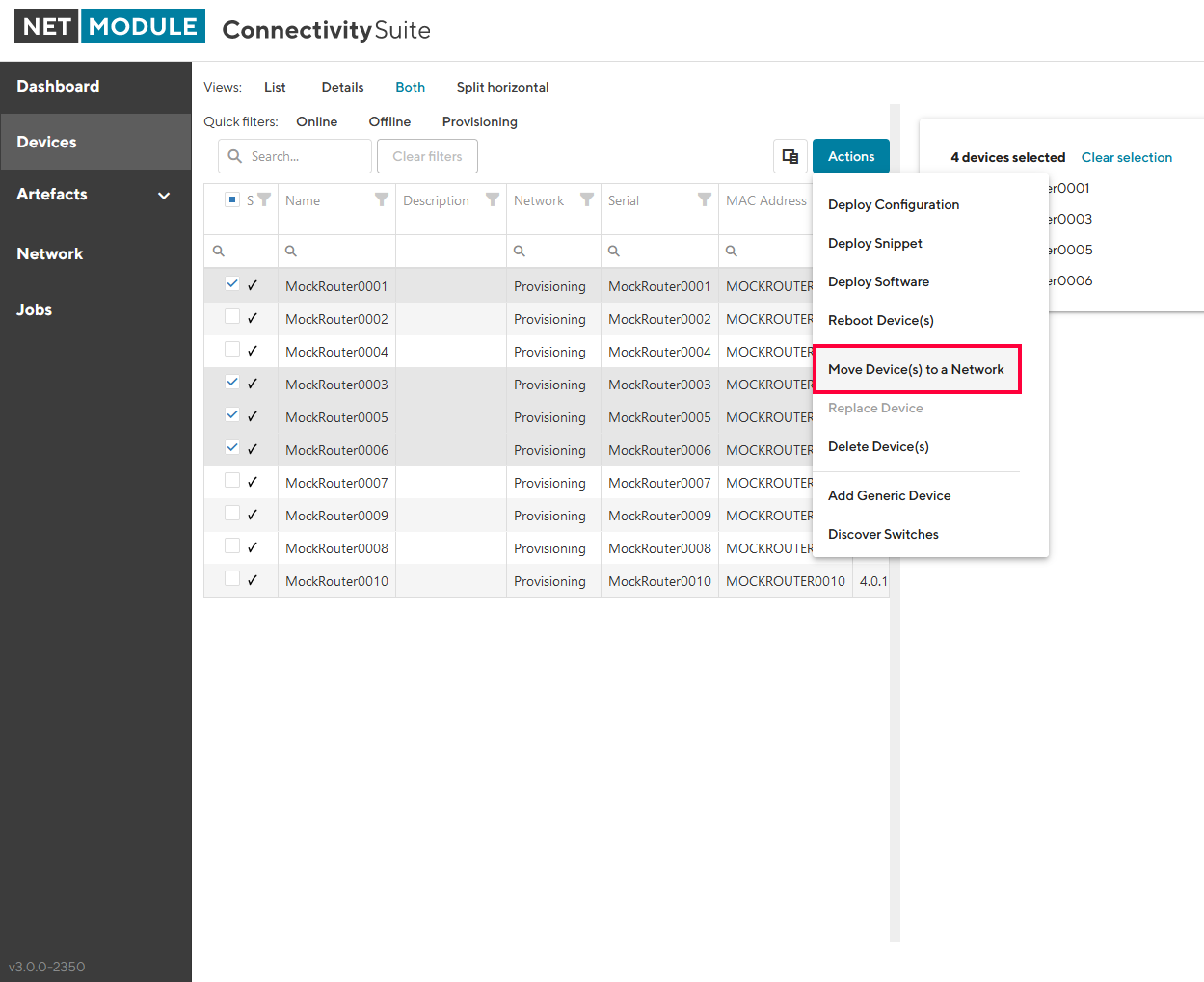
Fig. 6.25 VPN Network assignment
Navigate to the page “Devices” of the Connectivity Suite and select the Devices which have to be assigned to a VPN Network.
Click on “Actions” at the upper right corner of the Main dialogue box and click “Move Device(s) to a Network”.
Select the required VPN Network in the drop down list and click “Next”.
Click on “Start assignment” to assign the Devices to the VPN Network (this operation may take some time). A confirmation message must be pop up which confirms the assignment of the Devices to the VPN Network.
The applied VPN Network will be shown in the Main dialogue box in the table.
6.4.6. Delete a Device
Navigate to the page “Devices” and select the Devices in the main dialogue that are to be removed.
Click on “Actions” at the upper right corner of the Main dialogue box and click “Delete Device(s)”.
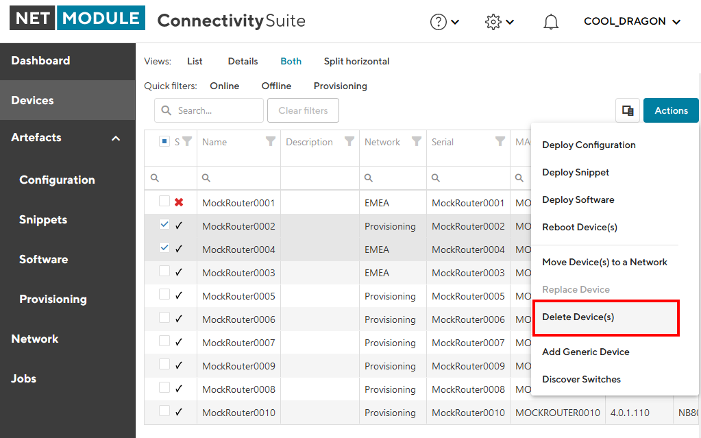
Fig. 6.26 Delete Devices Action
Confirm the deletion by clicking “Delete device(s)”.
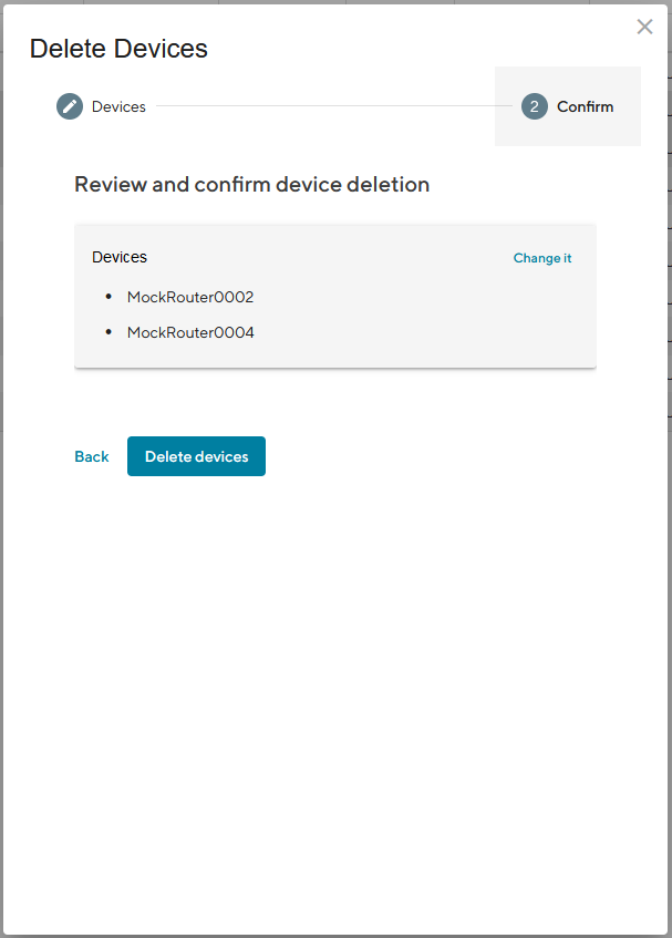
Fig. 6.27 Delete Devices Confirmation
6.4.7. Add a generic Device
Navigate to the page “Devices”
Click on “Actions” at the upper right corner of the Main dialogue box and click “Add generic Device”.
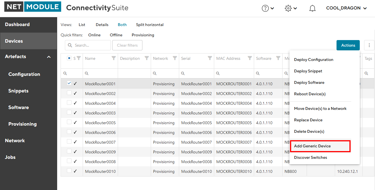
Fig. 6.28 Add Generic Device Action
Add the device by clicking “Add Generic Device”.
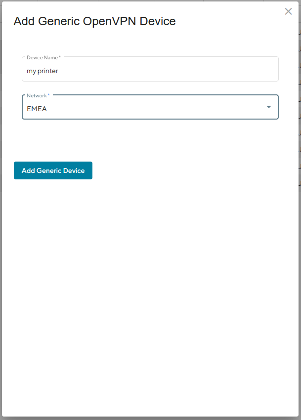
Fig. 6.29 Add Generic Device Dialog
You can download an OpenVPN configuration for the newly added device
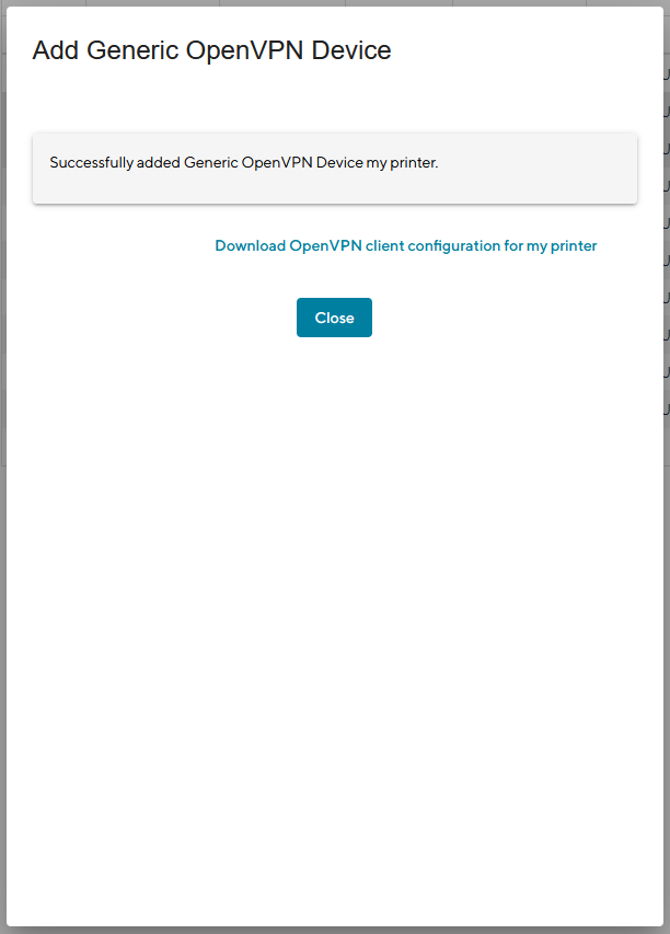
Fig. 6.30 Add Generic Device Confirmation
6.5. Router specific actions
6.5.1. Router Provisioning
Before the devices can be managed or accessed, they must be provisioned. Provisioning makes it possible to integrate the devices into the network infrastructure of the Connectivity Suite. The provisioning process is shown in Fig. 6.31 and described in the following chapters.
Caution
The Router Configuraiton must support the following, for proper operation through Connectivity Suite. | a. Open TCP port 22, for SSH access through VPN tunnel from CS | b. SSH Server listening on port 22 | c. root user with SSH access
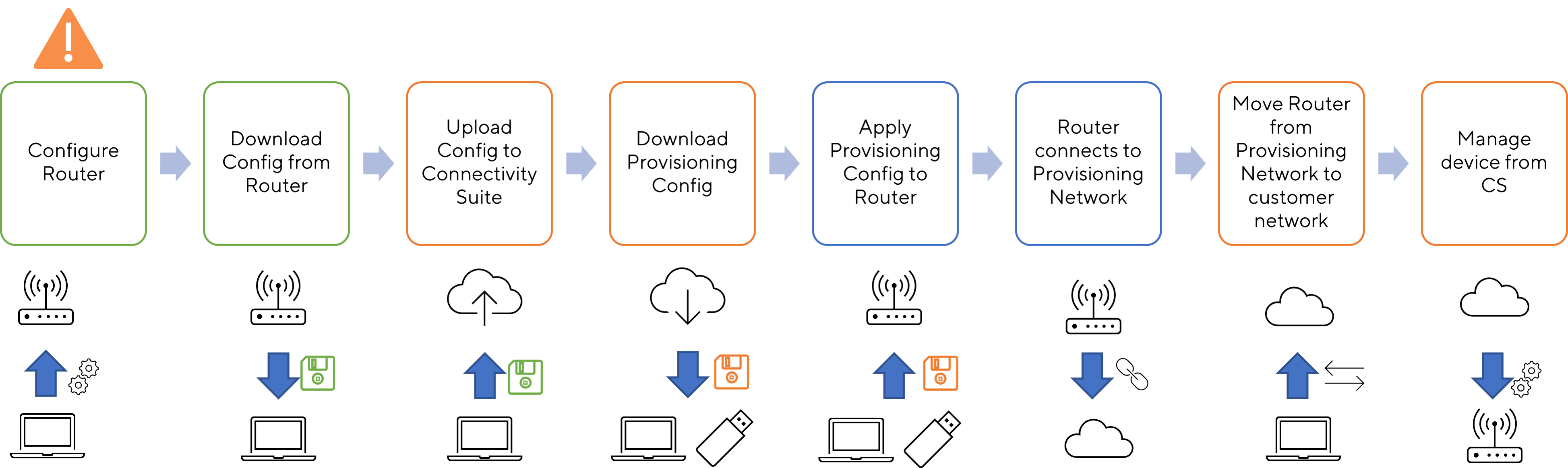
Fig. 6.31 Provisioning Process Router
Note
Only 250 devices can be connected to the Provisioning Network at once. If the provisioning server has no available space left move the Devices to a VPN Network before adding more.
For the following steps an account with Platform Administrator rights is required.
The CS can deploy configurations to Devices. The main feature here is mass configurations that can be rolled out for different types of Devices. In addition, configurations of individual devices can also be copied or adapted via the CS.
6.5.2. Router replacement
A NM router will be replaced due to a defect or a hardware update etc. If the replaced Device is not the same type as the replacement Device this procedure might won’t work.
Note
Ensure that the firmware used on the replacement Device is the same or newer than the firmware version of the Device being replaced, otherwise the replacement will not work and both Devices will be lost.
Navigate to the page “Devices” and click on “Actions” and “Replace Device” to exchange a Device.
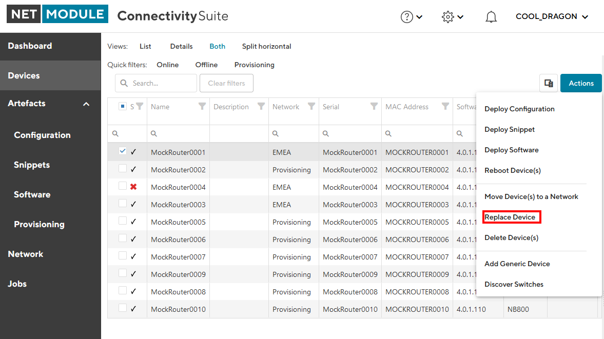
Fig. 6.32 Replace Device
Click “Generate Replacement Device Configuration” to generate a configuration which can be uploaded to the replacement Device.
Click “Download this configuration” (configuration can be uploaded via the web manager) or “Download this Configuration as USB version” Configuration can be uploaded via an usb stick) to download the configuration.
Upload the configuration to the replacement Device via web manager or USB
The replacement Device will automatically connect to the Connectivity Suite and the Device which will be replaced will be automatically removed from the Connectivity Suite.
If the device has connected correctly you can see all the Device details by clicking on the replacement device in the table of the Main dialogue box.
Changes to replaced Device object:
firmware version
Serial number
Note
When the replacement device connects to the Connectivity Suite, the certificate of the defective device will be revoked and it won’t be able to connect to the Connectivity Suite anymore.
6.6. Switch specific actions
6.6.1. Supported switch firmware releases
Before connecting a switch to the Connectivity Suite ensure that a supported switch firmware is running on the device. The Connectivity Suite guarantees support for all switch firmware releases which are supported by Tronteq. These can be checked at the following link: https://www.tronteq.com/
6.6.2. Switch provisioning
Before the switch can be managed or accessed, it has to be provisioned. Provisioning makes it possible to integrate the switch into the network infrastructure of the Connectivity Suite. The provisioning process is shown in Fig. 6.33 and described in the following chapters.
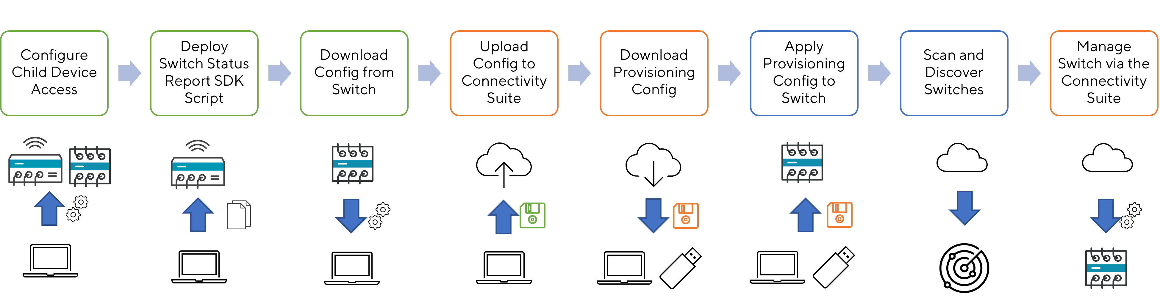
Fig. 6.33 Provisioning Process Switch
For the following steps an account with Platform Administrator rights is required.
Configure child Device Access: Configure a Child Device Access on the router for the switch as described in Section 13. Note that LLDP discovery must be enabled on the router before provisioning (LLDP sending is enabled on the switch by default).
Deploy Switch Status Report SDK Script: On each router where a switch is connected, the SDK script must be executed. The SDK script is provided by NetModule and can be downloaded from here: https://repo.netmodule.com/repository/cs/cs-stable/sdk-scripts/cs-status-reporting.are. To be able to run the script NRSW version 4.8.0.100 or above is required! See Section 9.4.2 on how to deploy this script via the Connectivity Suite. Choose “openvpn-up” as Event Trigger. After deployment, reboot the router to activate the script.
Download Config from Switch: Once the switch is configured the configuration can be downloaded from the switch. The file should be a .cfg file.
Upload Config to Connectivity Suite: Navigate to the page Provisioning and Upload the configuration (see Fig. 6.34). Fill out the required fields, upload the configuration and click “Generate Provisioning Configuration”.
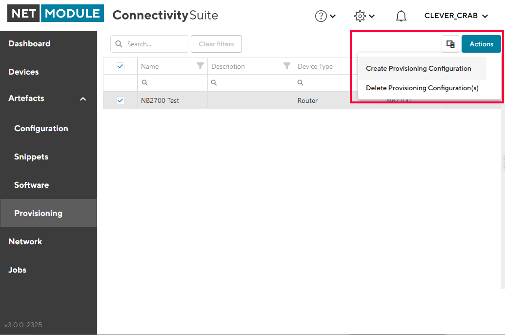
Fig. 6.34 Add Switch Provisioning Configuration
Download Provisioning Config: If the provisioning configuration is uploaded to the switch via a usb stick click on “Download USB configuration” or if its uploaded via the web interface of the switch click “Downoad file configuration” (see Fig. 6.35 ).
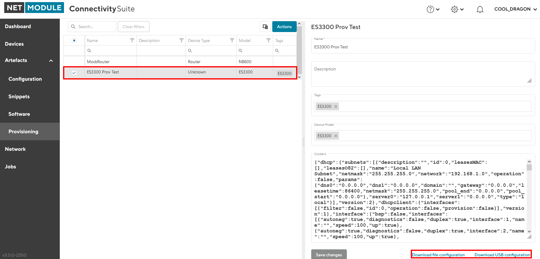
Fig. 6.35 Manual Switch USB update
Apply Provisioning Config to Switch: Upload the provisioning configuration to the switch, as mentioned before this can be done via usb stick or via web interface of the switch.
Scan and Discover Switches: Select the routers where the switches are connected to, open the “Actions” menu, select “Register Connected Devices”, and start the scan process. If switches are discovered they will be shown in the Devices List.
Note
The same provisioning configuration can be used for several switches as long as they belong to the same Device Model
6.7. WLAN Access Point specific actions
The AP3400 is being managed the same way as the ethernet switches.
Note
Once an accesspoint has been commissioned to Connectivity Suite, it is strongly advised to no longer managage the access point locally.
6.7.1. Firmware releases
All the firmware releases for AP3400, listed in the NetModule Soft- & Firmware repository are supported.
6.7.2. Provisioning
The provisioning of AP3400 is following the same process as for switches.